Part Number: TIDA-00817
Hello.
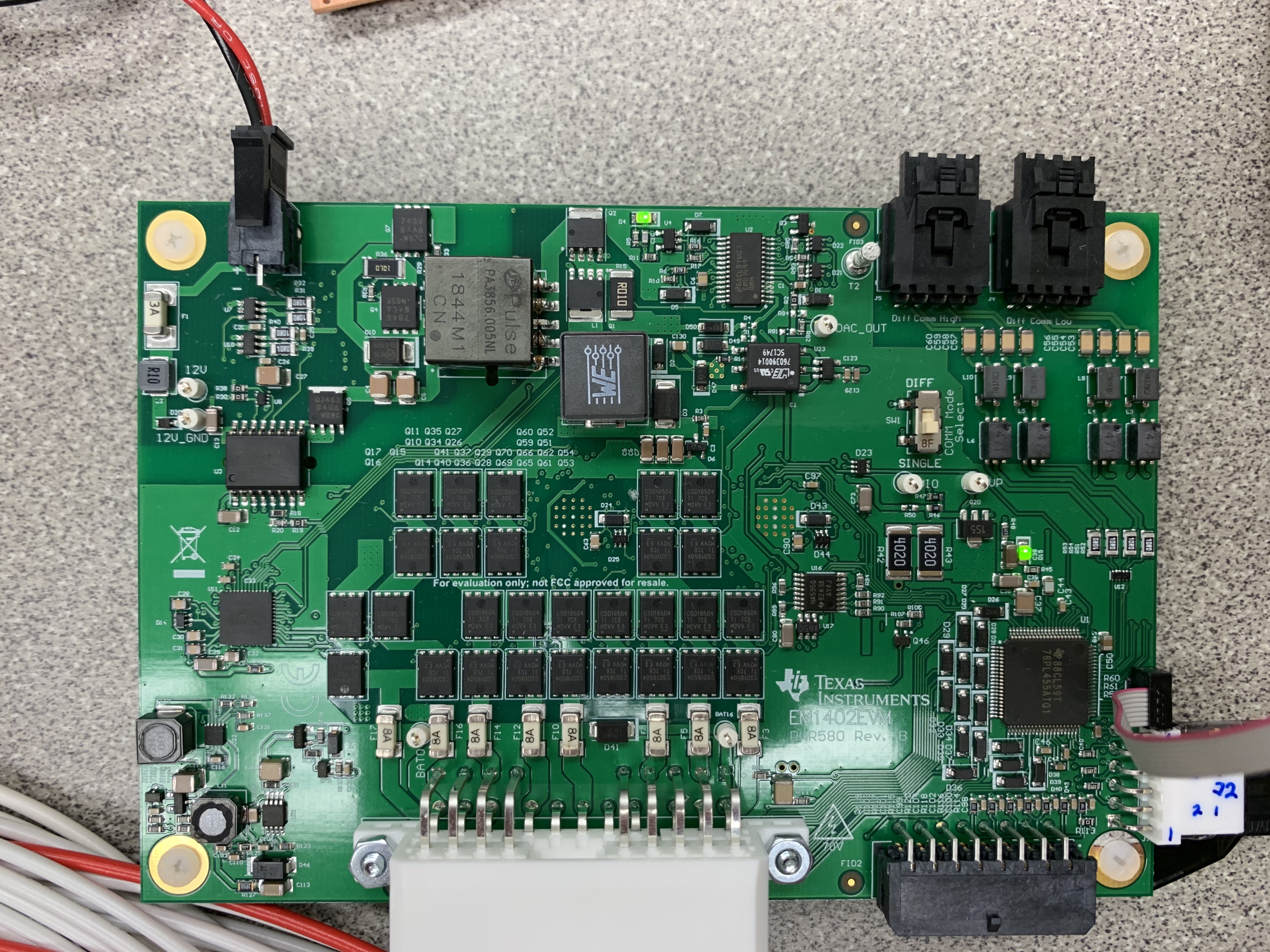
I'm working on the TIDA-00817 16ch active balancing BMS board.
After I found the TIDUBI0 document helping from the TI e2e community, I did the instruction from them.
In TIDUBI0, p13, to run the demonstration, it says do as follows.
1. Modify the TMS570LS0432 LaunchPad.
-> Yes I did the modifications.

2. Program the demonstration software into the TMS570LS0432 device.
-> I'm not sure this instruction. Does it means that install the http://www.ti.com/lit/zip/tidcci7
and run the sys_main.c code in CCS?
Anyway. I did install and run it with CCS.
3. Check the connections between boards and batteries.
-> I checked all the voltage of cells and 12V battery and other connection
4. Ensure the battery voltages are in the correct range.
-> It is in the correct range.
To start the demonstration, do as follows:
1. Run the demonstration on the TMS570LS0432 LaunchPad.
-> Is it also the same as I mentioned above?
2. Start the GUI on the host PC.
-> After I run the gui, It showed Unable to open com port.
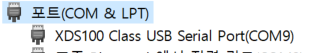
In Device Manager, Port shows above.
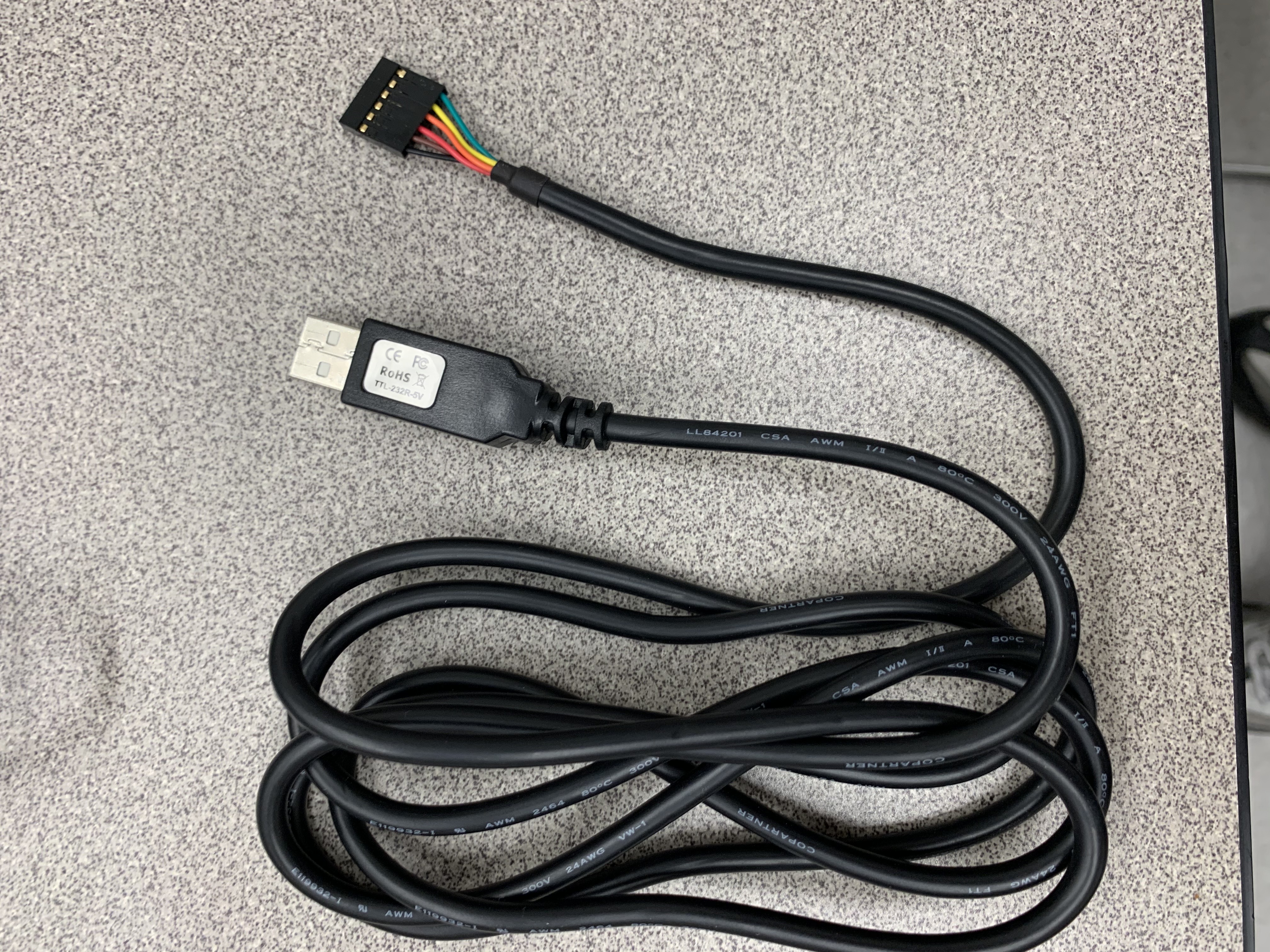
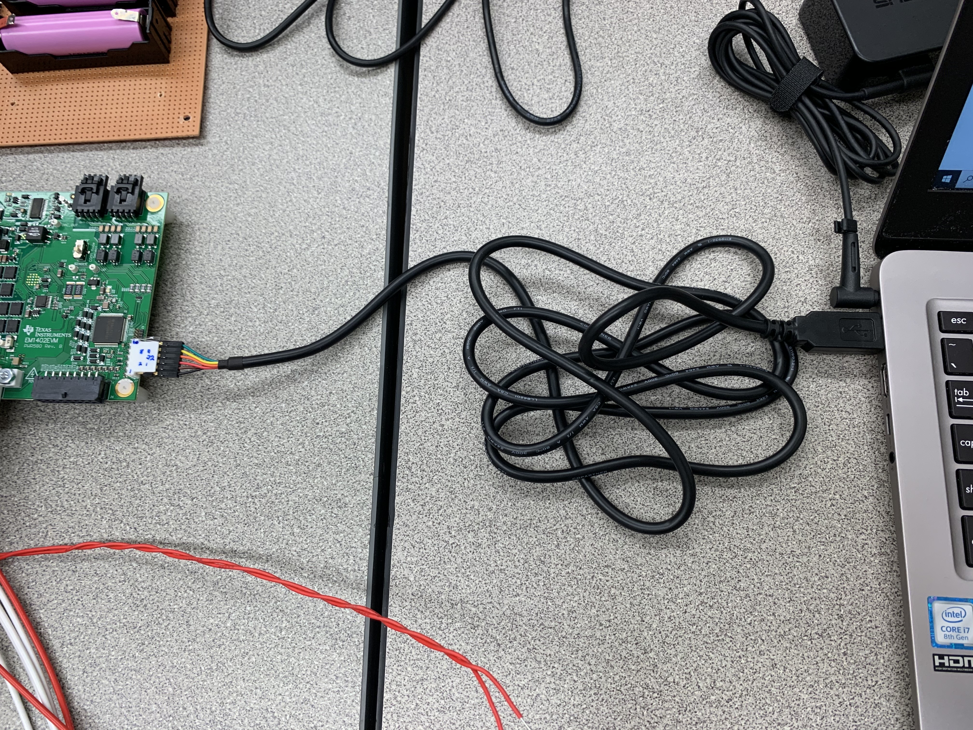
I checked with the usb to TTL serial cable delivered with EVM board to connect direct from BMS board to host pc.
It can allow me to enter gui.
In this condition, what can I do to solve this 'unable to open COM port' problem?
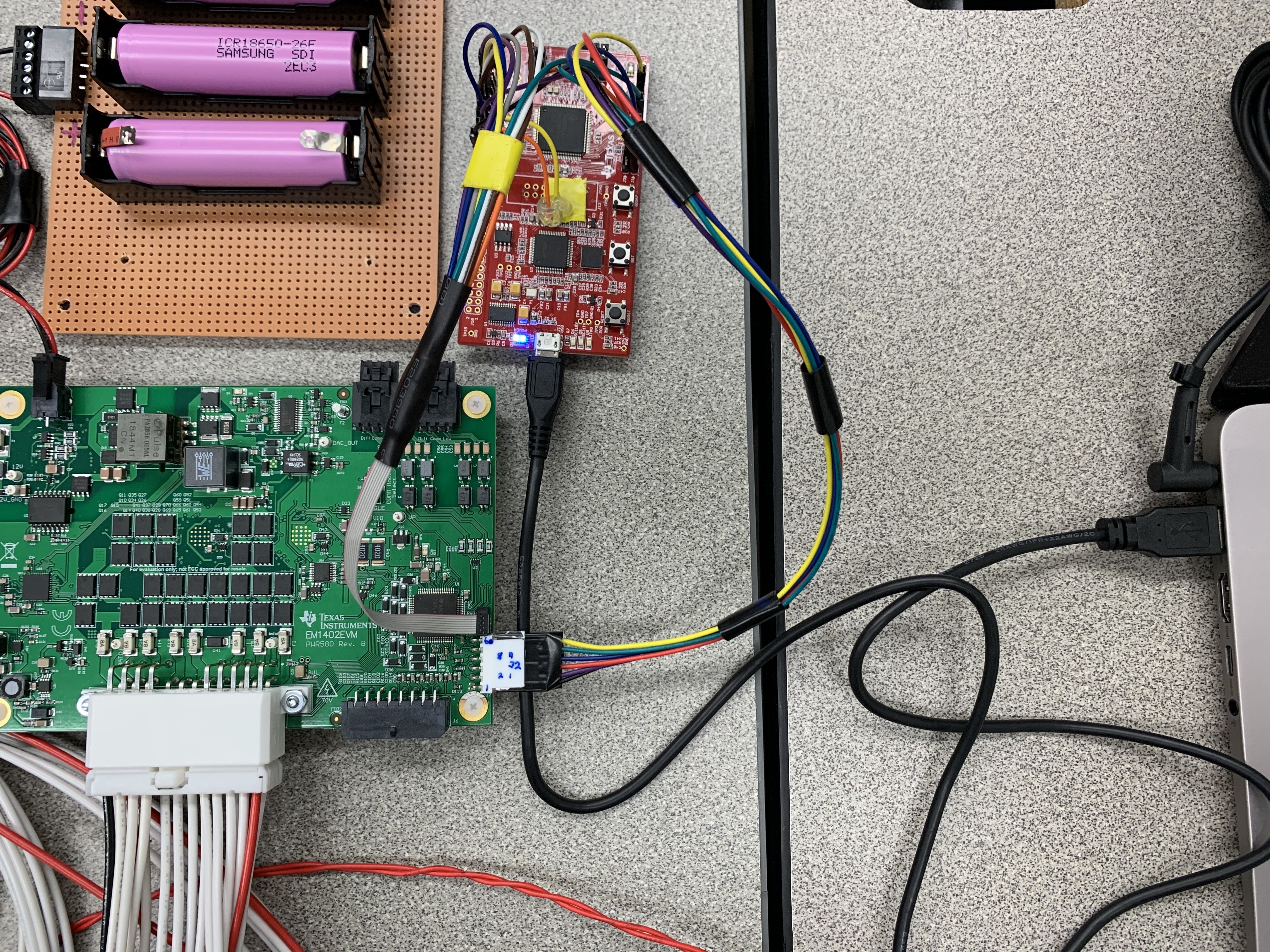
One thing I found the difference between direct connection and via tms570 is the LED lighting.
D4 is light on when I direct connect with bms board ,But when I connect via TMS 570, it is off state.
Thank you.