This thread has been locked.

If you have a related question, please click the "Ask a related question" button in the top right corner. The newly created question will be automatically linked to this question.

WEBENCH® Tools/UCC5390-Q1: UCC5390-Q1

Part Number: UCC5390-Q1

Tool/software: WEBENCH® Design Tools

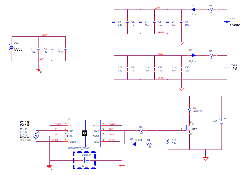
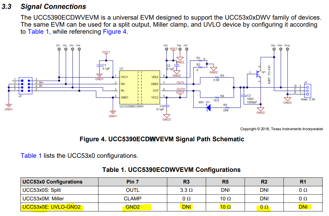
Im having trouble making this part work. I am following the UCC5390ECDWV evaluation module design to test a the circuit, but it is not very clear as what to do. Example, for miller configuration: R2 is removed. Does that mean leave it open, or just removed and replace by wire.

  • Hi William,

    For miller configuration of UCC53x0 in the EVM board, PIN 7 become CLAMP (drain of miller clamp NMOS), and is no longer GND

    So R2 needs to be removed to make an open circuit (not replaced with jumper) to properly configure the EVM for Miller configuration.

    In fact, anywhere in the table where it says DNI, that means to remove the resistor (open circuit). The only time you should populate with a jumper/0ohm resistor is when the table says 0hm for a certain resistor.

    If you put a jumper/0hm in R2, the the IGBT would not turn on at all, as Source/emitter would be shorted, and R4 may get toasted as well.

    I annotated Section 3.3 in the EVM User's Guide to show the configuration.


    I hope this helps. If i answered your question, please press the green button. If you have any other questions, please don't hesitate to ask.

    Best

    Dimitri James

  • Hi, thank you very much for the answer. That really help me. But i am confused about setting up the power supply(figure 3). I require a negative gate drive, but it seems like i will need 3 power supplies to get this done. Im i correct at this?. (Vcc1,bcc2,vee2).

  • William,

    **Could you clarify whether you are working with the physical EVM or Webench design?**

    If you are simulating the EVM design using the PSPICE model from the UCC5390-Q1 project folder, theres no special configuration that needs to be done. See Below.

    If you are using the physical EVM with UCC5390-Q1, you must provide 3 supply voltages: Vcc1, Vcc2, and Vee2.

    Vee2 would be the negative supply required for negative gate drive bias at turn-off. 

    (With the physical EVM, You can generate Vcc1 with 1 power supply. Vcc2 and Vee2 can both be generated on single, bipolar power supply)


    william diapis said:

    Part Number: UCC5390-Q1

    I am following the UCC5390ECDWV evaluation module design to test a the circuit...

    I thought you were asking about general UCC53x0MC parts which have miller clamp feature, but want to clarify to avoid confusion.

    To clarify, UCC5390-Q1 CANNOT be used in miller configuration at all, as it the Automotive qualified version of UCC5390EC (emitter-referenced UVLO) and doesn't have Miller clamp..

    If you require miller clamp with UCC5390-Q1, you must implement it externally. You also have to configure the physical EVM board for UCC53x0EC as highlighted below (and specified in User's guide)

    UCC5310MC and UCC5350MC are the options that have integrated miller clamp. 

    Please let me know if this helps. If this answered your question, click the green button. And do let me know if you have followup clarification or further questions.

    Best

    Dimitri