Other Parts Discussed in Thread: MSP-FET
Hello,
I have build the TIDA-010042, downloaded the firmware using MSP-FET and until that point all is working well.
Now I’m trying to test the functional behavior and I’m having problems that in my opinion comes from a wrong simulation of the battery.
- I’m powering the TIDA-010042 with an external power supply configured 18V@3A.
- The uC is powered also with the same power supply using jumper J3.
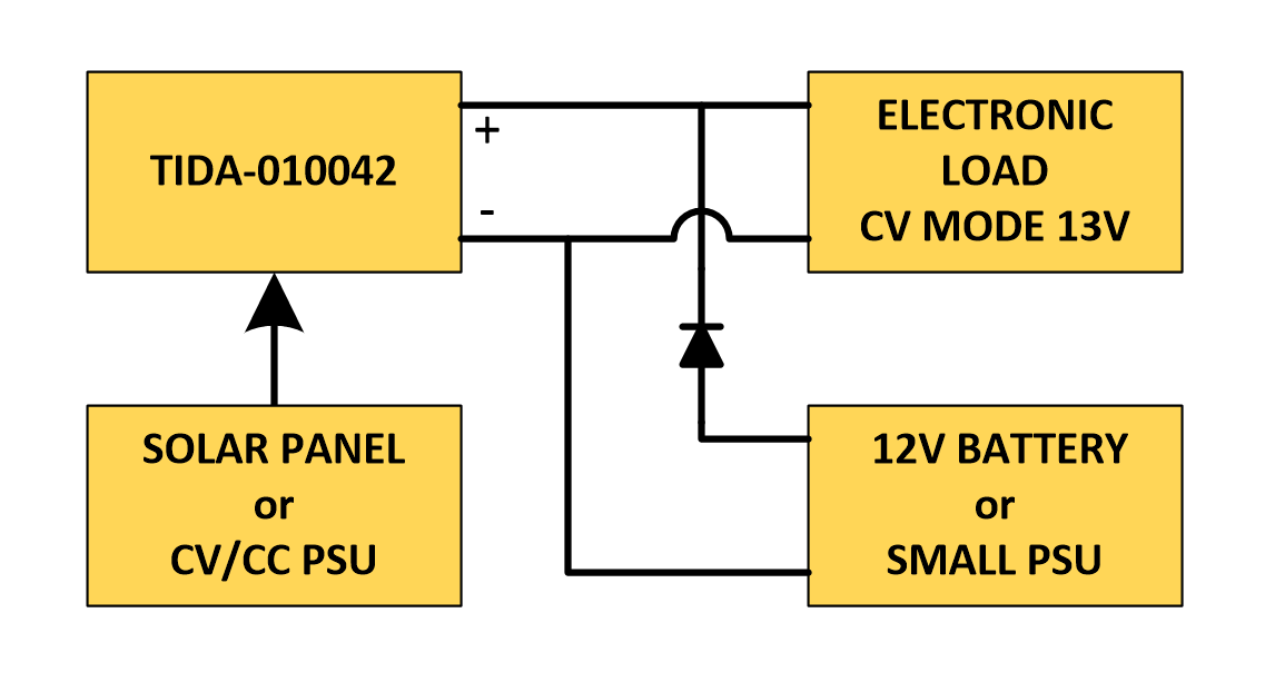
- In the battery output I have connected an electronic load configured in CC mode at 2A.
- For the load I have place a voltmeter.
When I power up the PSU and the electronic load the current goes to 2A but the Voltage measured by the electronic load is 17.6Vdc what is wrong. I can see that each 2 seconds aprox the system try to put the buck converter to work, the voltage decrease to 15V more or less for some milliseconds and after that goes to 17.6 doing it in a loop.
In your design guide on test setup part (pag 20) you specify: Connect the battery or electronic load to the battery connection (J5). This reference design supports 12-V, 24-V, or 48-V batteries. If using an electronic load to simulate a battery, set the load to constant current mode (CC) and to the respective voltage system regulates its voltage itself.
Could you please clarify how to proper simulate the battery with the electronic load?
Best regards and thanks in advance
Diego