This thread has been locked.

If you have a related question, please click the "Ask a related question" button in the top right corner. The newly created question will be automatically linked to this question.

TIDA-010074: MOSFET current Rating and SOA

Part Number: TIDA-010074
Other Parts Discussed in Thread: CSD19536KTT, , BQ76200

Hello;

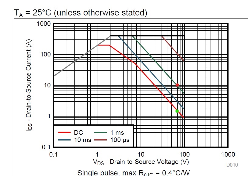
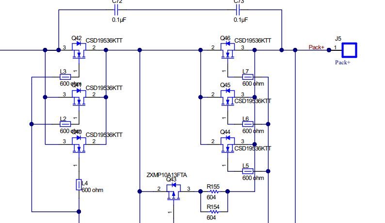
TIDA-010074 uses "CSD19536KTT"  Three , N-CH MOSFET, 100 V, 200 A .The Document says that it can handle 72 V and  30 A Discharge current .. So my question is if we look at this mosfet SOA the max Current at this voltage is 1A . If we uses a formula "Trise/(Vds*Rth)" i get 6.25 A  and if we mark this Vds and Id on th SOA curve the point is above DC line. That means if we want the same current then Vds need to come down nearly to 20 V.. So want to know where is this 30 A figure comming from or 10A per MOSFET Branch..

Thank You  .

  • Hello Peeyush,

    Thanks for your interest in TI FETs. I closed the duplicate e2e post. During discharge, the discharge FETs will be turned on and fully enhanced. Therefore, the voltage across the paralleled FETs will be very small and we are not as worried about SOA. Self-heating due to conduction loss (I2R) is the biggest concern when the FETs are on. SOA becomes a concern during turn-on and turn-off where the devices go thru the transition of blocking voltage to conducting current and vice versa. The switching times are determined by the external drive circuit using the BQ76200 driver IC. I am including links to blogs on SOA and MOSFET switching times below. I was not directly involved in this reference design and will submit this one to the team that did the actual design to further address your concerns.

  • Thanks for your Reply . So You mean to say i only need to check SOA in a transition region where switching losses are going on.And during these loses the SOA need not to coss the Pd line..In other words For a safe current Calculated by (Trise=Ids*Vds*Rth) the voltage need to come down so that the SOA region dont gets violated

  • Hi Peeyush,

    Correct. The battery application uses the MOSFET as a load switch.  When on the concern is normally heating from current through RDSON. When off the concern is typically the voltage rating.  During switching the voltage will rise or fall while current is also changing.  You want the switching time to be within the SOA limits of the part without being so fast to excite inductance in the system which could create a voltage spike and break something.   If a FET is already hot from operation when it switches off, its tolerance may be reduced, see the references John posted and other MOSFET information.