This thread has been locked.

If you have a related question, please click the "Ask a related question" button in the top right corner. The newly created question will be automatically linked to this question.

PSPICE-FOR-TI: Searching for Center-Tapped Transformer

Part Number: PSPICE-FOR-TI

Hi PSPICE-FOR-TI team,

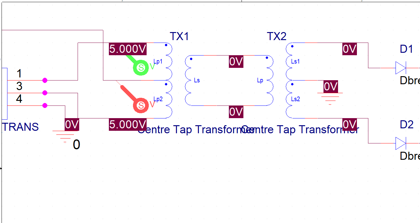
I am searching for a center-tapped transformer model like the one shown below to use and modify (turns ratio, inductance values, etc.) for use in a push-pull transformer system sinumlation:


On PSPICE's online library, they say such a model is available as "XFRM_LIN/CT-PRI/SEC," and their online forum lists a directory to find it which does not appear in PSPICE for TI.

Attempting to create a new center-tapped transformer model only gives me the option to place the center tap on one side of the model, as shown below:


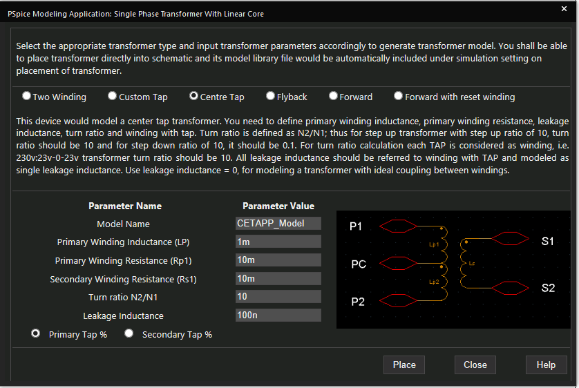
What needs to be done for me to access the "XFRM_LIN/CT-PRI/SEC" model or use a similar one?


Thank you,
Manuel Chavez

  • Manuel,

    It looks like you can select a center-tap for the primary, or the secondary, but not both.

    Could you place two transformers, one with a center-tapped primary, and the other with a center-tapped secondary, and connect the secondary of the first to the primary of the second?

    Would that work?

    Regards,
    John

  • Hi John,

    This has not worked so far. The transformer shows 0V in in the middle:


    The simulation waveform also doesn't appear to show to primary side of the transformer switching as expected.

    On a related note, is there a way to model two isolated GND potentials in PSpice for TI?


    Thank you,
    Manuel Chavez

  • Manuel.

    Please try providing a DC path to ground for one end of the secondary/primary connection. 

    It may matter which side gets grounded, but w/o knowing more, its hard to say.

    The time-domain waveform is the one to focus on for troubleshooting. 

    Pspice has a number of different ground connections in the PLACE GROUND menu.
    The ground symbols with a '0' in the symbol provide connections to node 0 in the circuit.
    These are absolute grounds that won't show any feed-thru or coupling between connections.

    The other ground symbols have other behavior/applications, but I am not familiar with the details. 
    More info is available in the HELP documentation, or possibly in the supporting forums.

    Regards,
    John

  • Thanks John,

    The DC path to ground didn't work, but perhaps I implemented it incorrectly. Do you mind if I share the file with you for some help?


    Thank you,
    Manuel Chavez