This thread has been locked.

If you have a related question, please click the "Ask a related question" button in the top right corner. The newly created question will be automatically linked to this question.

WEBENCH® Tools/LM3410: LM3410

Part Number: LM3410
Other Parts Discussed in Thread: , , LM3405,

Tool/software: WEBENCH® Design Tools

Hello TI support

I looking for a LED driver for a power LED that will be used as flash to camera.

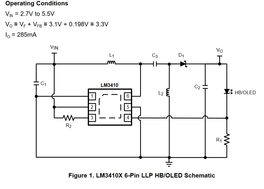
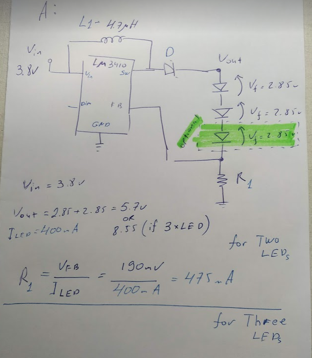
Vin to LED driver is 3.8V. (data sheet attached)

Vf of my LED is 2.85V @500mA

I would like connect 2 or 3 LED units in parallel for my application .For that, I decide that LED drive should supply up to 1A to LED and I chose - LM3410,LM3410-Q1.

1.Is LM3410 can be as good solution to my LED lighting?

2. Unfortunately i not clear understand what a different between LM3410 and LM3410-Q1.

3. Before starting of my design in purchased your EVB - LM3410XSDSEPEV because it can supply 320mA.

a. Can i play with value of R1 in order to increase LED current and get 500mA ?

4. In data sheet of LM3410 and LM3410-Q1,section 8.2.8  LM3410X  WSON:  Boost Flash Applicatio

You not used additional Indicator L2 that you used in LM3410XSDSEPEV (attached). 

while you add that L2 to LM3410XSDSEPEV and the current is 320mA and not 1A as in data sheet? Please suggest when i need add L2 to my application?GW CSHPM1.PM_EN.pdf

  • Hello Ilya,

    I would like connect 2 or 3 LED units in parallel for my application .For that, I decide that LED drive should supply up to 1A to LED and I chose - LM3410,LM3410-Q1.

    1.Is LM3410 can be as good solution to my LED lighting?  Are you stating 1A per LED or 1A total output current?  The LM3410 has a peak current limit of 2.1A to design to.  1A at 2.85V output will work with the LM3410

    2. Unfortunately i not clear understand what a different between LM3410 and LM3410-Q1.  -Q1 is automotive grade.

    3. Before starting of my design in purchased your EVB - LM3410XSDSEPEV because it can supply 320mA.

    a. Can i play with value of R1 in order to increase LED current and get 500mA ?  Most likely it will be okay if the LED is changed, the inductors can handle the current, it would be best to go through the design calculations for the higher current to verify.

    4. In data sheet of LM3410 and LM3410-Q1,section 8.2.8  LM3410X  WSON:  Boost Flash Applicatio

    You not used additional Indicator L2 that you used in LM3410XSDSEPEV (attached). 

    Your input voltage is 3.8V and your output voltage is 2.85 +/- ??.  The boost application is for when the LED forward voltage is higher than the input voltage.  If you chose to put your LEDs in series you could use the boost circuit.  The EVM, LM3410XSDSEPEV, is a SEPIC converter.  It allows the input voltage to be both higher and lower than the LED voltage.  If your LED voltage is always below your input voltage (with the added current sense voltage drop and other voltage drops) you could use the LM3405.  This depends on how low Vin gets with respect to how high VLED can be (all tolerance including operating temperature).

    So, if you place your LEDs in series you can use the boost configuration.

    If your input voltage can be higher and lower than VLED the SEPIC would be the choice

    If your input voltage is always higher than VLED (with margin) you could use the LM3405.

    This depends on what the output power is, VLED and ILED total of all LEDs.

    Best Regards,

  • Hello

    Thank you for clear explanation, unfortunately i not have experience to work with LED drive and your clear answer very help me !!! 

    1. in order to privet misunderstood:

    You add additional Indicator L2 in LM3410XSDSEPEV because Vout can be low then Vin, yes?

    2. Because I bought LM3410XSDSEPEV (I think I made a mistake in choosing EVB, because in my solution i have two or three LED in serial connection (see attache schema). better For that i needed buy LM3410XBSTOVPEV )

    please guide me, what should be a changes on LM3410XSDSEPEV in order to connect two serial  LEDs. Each LED Vf=2.85 +/- 0.15V.

    Do i need remove L2 and C3 from LM3410XSDSEPEV?

    3. Can you please help me with schema for my solution (Even drawing with a pencil can help, I'm just a little confused by most of the options you have).

    I have Vin=3.8V (this is come from DC/DC), LED: Vf=2.85 +/- 0.15V. Iled=400mA

    Is my attached schema drawing correct ?

    4.

    5. In order to understand how LED driver work, can i say:

    that Vout equal to Voltage drop on LEDs = Vf?

    The current through LEDs is--> Iled=Vfb/R1? And Ileds depend of R1 value?

    6. Unfortunately, i not understand, what a difference on components value: L1,D, R1 if i will use with three LED (Vf=2.85) or two?. I need that my current through two or three LEDs will be constant 400mA.

    Vout = 2.85+2.85+2.85=8.55V is not a part of calculation, i think i missing something, what is it?

    Thank you

    Ilya

  • Hello Ilya,

    If you are going to modify the SEPIC to run as a boost you have to make it look like the BST schematic.  The extra inductor and capacitor are for a SEPIC design, it operates different than the BOOST.  A SEPIC can have higher or lower voltage than the input.  It is a more complicated design.  If you can arrange you LED load to be in series so Vout is always higher than Vin a BOOST is what you want to use.  Note that if you go with a boost and place one LED on the output you can damage the circuit.  If you look at the boost schematic, Vin goes to the inductor then the diode so a short on a boost output is a diode drop short of Vin.  If you convert the SEPIC to a boost makes sure you don't try to power the board on with the single LED.  To change to a boost remove L2 and short C3 AND remove HB/OLED.  Also make sure that at least two or three LEDs are connected in series when powering the board up since it does not have OVP and can damage the circuit.  The datasheet shows an OVP circuit to protect from open LED string if you want to add that.

    Your schematic is correct, always have at least two leds on the output.  Also, before powering on you may want to use a lab supply to verify your LEDs are wired correct and the forward voltage is higher than the input you will be applying.

    Output current is 0.19V/R1, R1 should be 0.475 ohms for 400 mA, you can set R1 higher for first testing to keep the current lower.  If you leave the present values it will provide 285 mA.

    Vf of the LED is the forward voltage at a specified current, 2.85V is typical for 350 mA operation for this LED.  At 400 mA it will be about the same.  If you look at the data sheet it will have a Vf versus current curve.  At 100 mA the Vf is 2.65V typical.

    that Vout equal to Voltage drop on LEDs = Vf?   Yes

    The current through LEDs is--> Iled=Vfb/R1? And Ileds depend of R1 value?   Yes

    The LM3410 regulates current so adding another LED will keep the current regulation the same, the input power will go up since the output power has gone up by 50% (three LEDs versus two)

    Vf two LEDs is 2.85 X 2 = 5.7V, Vf three LEDs is 8.55V, Output power two LEDs is 5.7V x 0.4A = 2.28W, output power three LEDS is 8.55V * 0.4A = 3.42W.

    Best Regards,

  • Hi Irwin


    Thank you for a clear explanation, i made all changes on LM3410XSDSEPEV - I removed L2, shorted C3 and removed HB/OLED and assembled my LEDs and it's work very well. On my final schema i will add OVP circuit.

    Just so you know, because your clear explanation and support i will used a LM3410 instead of FAN5333ASX.

    Last questions:

    1. You have three packages - WSON, SOT-23 .... what is your suggestion?
    2. You have two types of Switching - 1600khz and 525KHz, which one is a optimal for me ? i will used - 400mA-600mA for one sec.
    3. You write - if i have 2 LEDs = 2.28W, 3LEDs=3.42Wif i will used a LEDS as flash for a pictures. Why this figure(power) is important to me? LED should have big footprint for heat distribution or this is influence to LM3410 ?

    Thank you

    Ilya

  • Hello Ilya,

    MSOP is easiest to heatsink for more power dissipation, WSON is in between, SOT-23 is probably the easiest to layout but is limited in power dissipation.  See table 6.4 on the bottom of page 4.  If this is a flash application where the pulse current is 400 mA you probably can use the SOT-23.

    1.6 MHz or 525 KHz depends on what you want your design to do.  If it needs to be small 1.6 MHz will allow the use of a physically smaller inductor.  525 KHz may be more efficient but, most likely, larger.

    I just calculated the power for two and three LEDs at 400 mA,  What is the worst case duty cycle when the flash is being used?  Longest on-time and shortest off-time?

    Best Regards,

  • Hello Irwin,

    Regarding your questions: duty cycle and longest on-time. Sorry, but this my first time of "flash" solution, i think the on-time will be no more one second and like that three times ( we would like get three picture one after one). If you have any opinion or suggestion i will be glad to get one. :)

    Regarding switching -  I decide to work with LM3410XMFE/NOPB (SOT-23 & 1600khz) and implement inductor P/N:SLF6028T-100M1R3-PF

    10uH, 1.8A,  63.8mOhm, Case- 2424.

    I still don't know if two or three LEDs with 400mA, or maybe I will need 700mA - (decide of that will be on the final solution ) Th requirements is - illuminate for a range of 6 m - Is the mentioned inductor 10uH and LM3410 case SOT23 is good solution to me?

    Best Regards

    Ilya

  • Hello Ilya,

    It should work fine at 400 mA, at 700 mA the current will be higher and the inductor chosen may still work, you can always go to the 4.7 uH in the same family.  Three LEDs at 400 mA will be close to 1A in the inductor, Since this is a flash application temperature rise probably is not a concern even at 700 mA.

    The current ripple is fairly low with 10 uH so you could just try the 4.7 uH to start out with.

    Best Regards,

  • Hi Irwin

    Sorry if i am asking many questions, i would like learn from professionals :)

    Can you please explain to me, why with 10uA a ripple is fairly low then 4.7uA?

    Why you suggest to start with 4.7uF ? (as i know i need get ripple in output as low as it can be, this is why i choose 10uA. I am right? ).

    what is advantage and disadvantage?

    Thank you.

  • Hello Ilya,

    Note that when calculating with 60% duty is when the MOSFET is on (no current goes to the output), 40% duty when the MOSFET is off and the inductor is supplying current to the load from Vin.

    In a boost converter the output current is discontinuous, the input current is continuous.  The MOSFET turns on and charges the inductor.  The MOSFET turns off and feeds the load sourced from Vin.  The output current ripple will be about the same for both inductors due to being discontinuous.  The only difference is the slope of the inductor current charging and discharging.  V = L * (di/dt).  Duty cycle for three LEDs on the primary side is approximately 60%.  At 1.6 MHz the MOSFET on-time is (1/1.6 MHz)*0.6 = 375 ns.  di = (V/L) * dt = (3.8V/10 uH)*375 ns = 142 mA peak to peak ripple in the inductor (for 10 uH), at 4.7 uH this becomes 303 mA peak to peak.  This is on an approximate 1A square wave.  Output current of 400 mA at 40% duty cycle (the secondary conduction time), this means the average current during the MOSFET off-time with the inductor supply current to the load at 40% duty cycle becomes 400 mA/0.4 = 1A.  The inductor ripple changes that shape to mostly a square wave with a slope at the top.  It starts at 1A + 303 mA/2 for the peak and ramps down to 1A - 303 mA/2 at the end of the secondary side conduction, 1.152A dropping to 0.848A for the 4.7 uH.  The rms current of this waveform will basically be about the same as if it were a 1A square wave at 40% duty cycle therefore this is low ripple.  For 10 uH the peak becomes 1.071A and dropping to 0.929A at 40% duty cycle.  The RMS current for 4.7 uH, 10 uH and infinite 'L' (square wave) will calculate all about the same.

    Best Regards,

    So the output ripple with these value inductors has very little to due with the output ripple of a boost due to being discontinuous.

  • Irwin

    Thank you for all support that you gave.

    Ilya