This thread has been locked.

If you have a related question, please click the "Ask a related question" button in the top right corner. The newly created question will be automatically linked to this question.

Changing output for a single boost circuit

Other Parts Discussed in Thread: LM2735

Hello,

Suppose Im deriving a 12V output using boost circuit having maximum Iout of 120mA. But if I connect a resistor in parallel to one of feedback resistor and connect a switch in series. This switch when closed would form a parallel connection with one of the feedback resistor. This would change the output voltage. For my requirement I need to switch output between 12V and 22V keeping other components same and other parameters same.

Attached is the Webench report in which the design inputs i have given were to give output voltage 12V but i have created the above scenario by changing one feedback resistor(which is similar to equivalent resistance for parallel combination when switch is closed) to produce output voltage is now 22V. WBDesign39.pdf

Is this possible to achieve? If yes then can you confirm that the parts used in the design are modeled correctly. This would ensure me that after building the circuit the tested efficiency would match with the efficiency given in the Webench report.

Thanks

  • Hi Sahol,

    Yes, it is possible to achieve design with Vout of 22V  with proposed change of one feedback resistor in 12V design.

    Proposed design for Vout of 22V is quite stable and doesn't violate the min duty cycle limit as well.

    The Webench models are based on actual measured data with acceptable accuracy. of +/-3to 5% between actual bench and Webench efficiency.

    At light load its difficult to predict and model the efficiency very accurately.

    Hence we might see bigger difference at light load between actual bench and Webench efficiency.

    We see only way to accurately predict efficiency is using a EVM board.

    We are not sure if same Cout will work for both 12V and 22V.This needs to be verified. Moving the post to product expert to suggest the feasibility of parallel resistors and a series switch arrangement.

    Thanks and Regards,

    Umayal

  • Hi Umayal,

    Any update from product expert regarding my query?

  • Hi Sahol,

    our team will support this case and will reply you in these two day.

  • Hello Jasper,

    Thank you for the reply.

    There is slight change in requirement. Instead of switching from 12V to 22V I need to switch to 24V. The IC chosen has max output voltage as 24V hence i think i should be fine. Let me know if Im correct.

    Attached below is the Webench report showing 24V output but having design inputs as 12V output voltage. Please review the report and let me know if the report is fine and all the components expect feedback resistor can be kept same or not. 24V 120mA 85C LM2375YQ1.pdf

    • Also can you suggest me more parts/designs for which the output voltage switching is possible without changing any component except the feedback resistor. In earlier messages I have specified my requirements for efficiency, output current etc. You can refer that. 

  • Hi Sahol,

    LM2735Y(520kHz Fsw) should be able to output 24V from 3.3V Vin and be configured as you said.

    You may need to use higher voltage rating components for rectifying diode and Cout. For rectifying diode, please use a 40V rating schottky diode. For Cout, ?40V rating ceramic capacitor is recommended.

    Make sure the inductor saturation current is at least 2A.

  • Thank you for the reply.

    Can you tell me what would be the inrush current based on current design?

    If the inrush current is above 1A what value of output capacitor should I use to get a inrush current upto 1A?

  • Hi Sahol,

    Sorry I didn't understand the question. Why are you worried about the inrush current? Do you hope to get a lower inrush current less than 1A?

  • My application is battery powered. The input to the boost is provided by the battery. At power up due to inrush current and battery esr the input voltage can be dropped significantly. This can cause the boost to reset. That's why I wanted to know what would be the inrush current based on design. If it's way high like 1.5A - 2A then it needs to be reduced to 1A by changing the output cap value.

  • Hi Sahol,

    There is LM2735 Pspice model on ti.com for simulation. You can use the model to simulate the inrush current.

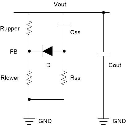
    If the inrush current is still too high, an external soft-start circuit shown as below can be added to reduce the inrush current. You can use 22nF for Css and 10kohm for Rss.