Hi TI Expert ,
I just build a Phase Shift FB converter prototype by exactly copy that PSFB circuit and gerber from PMP8740.
( but I did not use the micron control , just using manual analog control of the CC/CV ).
It is my 1st time to study PSFB . I use a 400V DC power to power this poto type ,
it work and I just operate to charge a 100AH 36V Lead Acid battery at no large than 6A.
I won't add more charge current because I'm not sure that FB waveform is healthy or not.
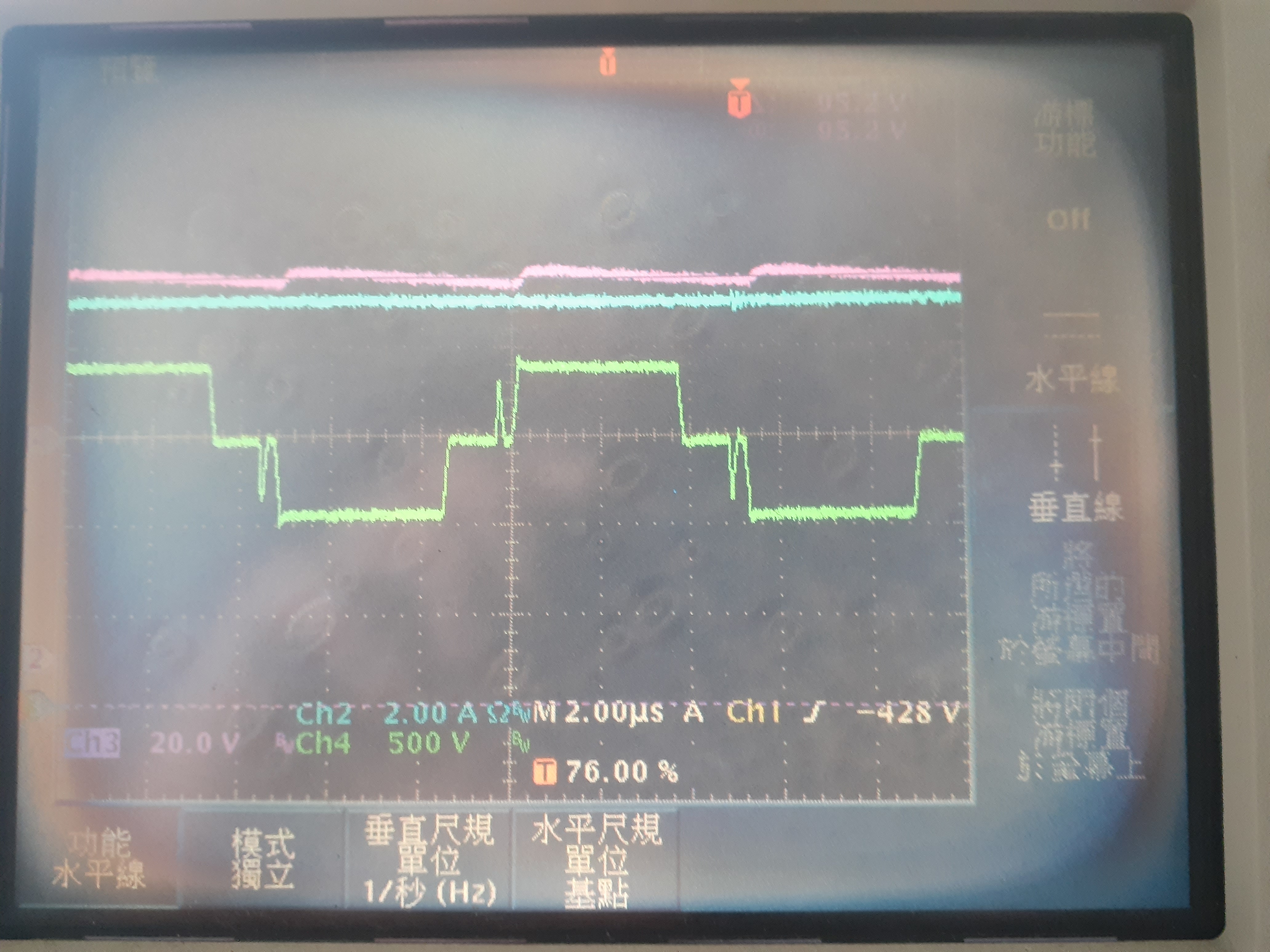
FB waveform in yellow color is attached by differential probing between FB MOSFET Q15 & Q16 Drain electrode
and I also add OUT E and OUT F waveform ( one in blue , one in pink ) to compare the timing.
I notice whenever a High to low on OUT E or OUT F , there always has a spike-like waveform on FB
My question is if this spike-like normal ? why it appear ? seems it trigger the OUT E or OUT F H to L,
or vice versa . I try to read some PSFB paper , just can't explain that on my own . Thank you for help!
Best regards,
Norman