Because of the Thanksgiving holiday in the U.S., TI E2E™ design support forum responses may be delayed from November 25 through December 2. Thank you for your patience.

This thread has been locked.

If you have a related question, please click the "Ask a related question" button in the top right corner. The newly created question will be automatically linked to this question.

generic Spice model extraction from TINA-TI

Other Parts Discussed in Thread: ADS8681, TINA-TI, TRF37D73

I followed this video to create a generic spice model for ADS8681.

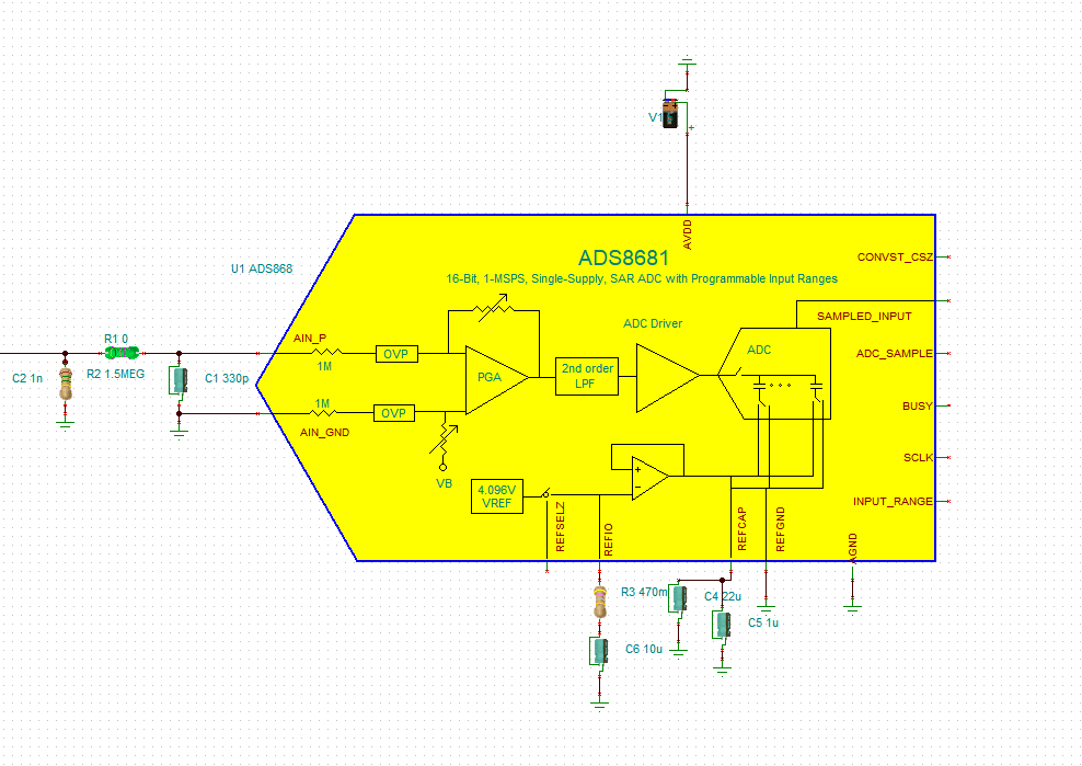
This is the model in TINA TI.

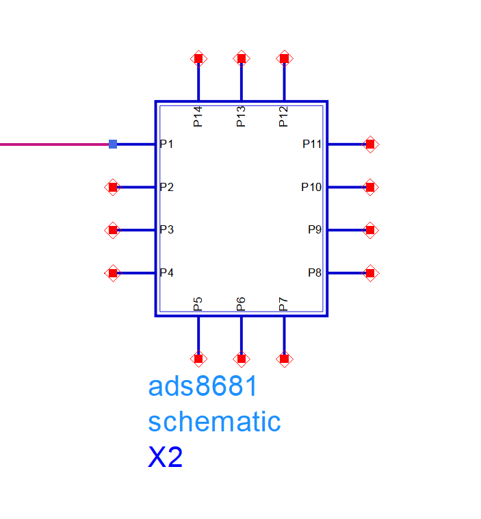
I import the generic spice model into Keysight ADS and it looks like this. 

My question is, how to know what this P1, P2, P3 is referring to? I need to know the P1, P2 names so I could connect them to the correct circuit. In TINA-TI, I able to see that but not in the generic model; it's not there!

Will I able to connect RF front end such as LNA and simulate the generic model by changing the sampling rate and etc.? 

  • Pragash,

    I'm sure there is some sort of training material that comes along with your third party Keysight ADS tool.  Generally speaking, when a generic model is imported into a simulation tool it only gives you a square box with 'pins' that you would need to futher define in the simulation environment.  The ADS8681 TINA model has 14 pins on it, and the imported symbol to Keysight also has 14 pins.  Which Px in your import maps to the TINA model is not something we'll be able to tell you.  Chances are P1 is AINP and then the rest follow around your box, but that should be documented in your tool import details.

  • Hi Tom,

    If TI doesn't know this information, Keysight doesn't know because this is the TI model, not the Keysight model!

    there is no document as far as my knowledge in ADS that define the PINs

  • Hi Tom,

    If TI doesn't know this information, Keysight doesn't know because this is the TI model, not the Keysight model!

    There is no document as far as my knowledge in ADS that define the PINs.

  • PIN and PORT definitions come from the Keysight tool, ultimately you may have to enter the TINA macro and build simular function in Keysight ADS. 

  • Hi Tom,

    Tell me if its make sense. Spice Model is TINA-TI model from TI. TINA-TI is software by TI. I generated generic spice from TINA-TI using TINA-TI spice model. But TI doesn't know the pin definition which matches generic spice, and Keysight should know just because I import the generic model into keysight. Does it make any sense? 

  • Hi Pragash,

    I know!  Crazy isn't it? 

    Actually, TINA and TINA-TI are from DesignSoft, not Texas Instruments.  If you install the TINA-TI software and look into the macro for the ADS8681 model, you'll find this entry:

    .SUBCKT ADS8681 INPUT_RANGE ADC_SAMPLE REFCAP REFGND REFIO AVDD REFSELZ
    + AIN_GND CONVST_CSZ AGND SCLK SAMPLED_INPUT AIN_P BUSY

    There are 14 entries that define the ADS8681 subcircuit.  It would be a resonable assumption that Keysight ADS assigned P1 to INPUT_RANGE, P2 to ADC_SAMPLE, P3 to REFCAP and so on through P14 as BUSY. 

    The unfortunate thing here is that the ADS8681 model is actually encrypted (I didn't realize that until now) so it may not work with your tool.  It's probably easier to just use the TINA-TI tool to determine if your desired front end is going to settle properly.

  • Thanks Tom. i have two problems in simulating in TINA-TI.

    1) we are using BAT62 diode in the design. how do i model the diode? any example videos will help. they don't have spice model so probably I need to insert diode parameters on generic diode model. 

    2) we also need a generic amplifier/LNA model. the model can have just gain also. we need some kind of gain block. does TINA-TI have it? 

  • Hi Pragash,

    In the TINA schematic editor, you can place a Schottky diode.  It's under the Semiconductors Tab, 7th symbol.  The tool defaults to a 1n581 I believe, but if you double click on the placed component, there is a radio button beside 'type' that allows you to choose a different model.  You can then edit whatever property you like to get something in the neighborhood of the BAT62 you seek.  Also under the semiconductors tab, you can choose 'Operational Amplifiers'.  Place an amplifier on your schematic and double click on it.  Use the radio button beside 'type' to choose a specific amplifier model or simply edit the parameters of the default 'generic' model.

  • please refer to reply below.

  • On OP-AMP, actually, I'm looking for RF AMP and not OP-AMP. i need gain and maybe noise figure but OP-AMP wont have it.

  • Hi Pragash,

    You can take a look at our RF Amplifier portfolio, some of these (like the TRF37D73) have TINA-TI reference models available.

  • Hi Tom,

    Thank you so much. I have a final question. I have an antenna also in the circuit. Does TINA TI have generic antenna I can set their parameters? If it doesn't, can I inject RF signal into the circuit for testing? 

  • Hi Pragash,

    I don't bellieve TINA-TI has an antenna, however, wouldn't the antenna just look like an ideal AC signal in series with an impedance?   You should be able to use an AC source in series with an R-L-C circuit that mimicks your antenna impedance.

  • Hi Tom,

    Thanks for the reply. Yes, I came across the AC source, but it does not have a frequency of operation. I want AC with a particular frequency to be injected to the circuit. Do you know how I can do this? 

  • Sure - place a 'Voltage Generator' from the Source tab in your schematic.  After it is placed, double click on it to get to the properties.  Go to the line that says 'Signal' and change the unit step to (as an example) Sinusoidal and enter a frequency and magnitude.