This thread has been locked.

If you have a related question, please click the "Ask a related question" button in the top right corner. The newly created question will be automatically linked to this question.

WEBENCH® Tools/LM5175-Q1: The time it takes for the output to go down from 12V to 5.5V

Part Number: LM5175-Q1
Other Parts Discussed in Thread: TINA-TI, LM5176-Q1, , LM5176, CSD17304Q3, CSD19502Q5B, CSD16415Q5, CSD17573Q5B, CSD18514Q5A, CSD18533Q5A

Tool/software: WEBENCH® Design Tools

Hi,

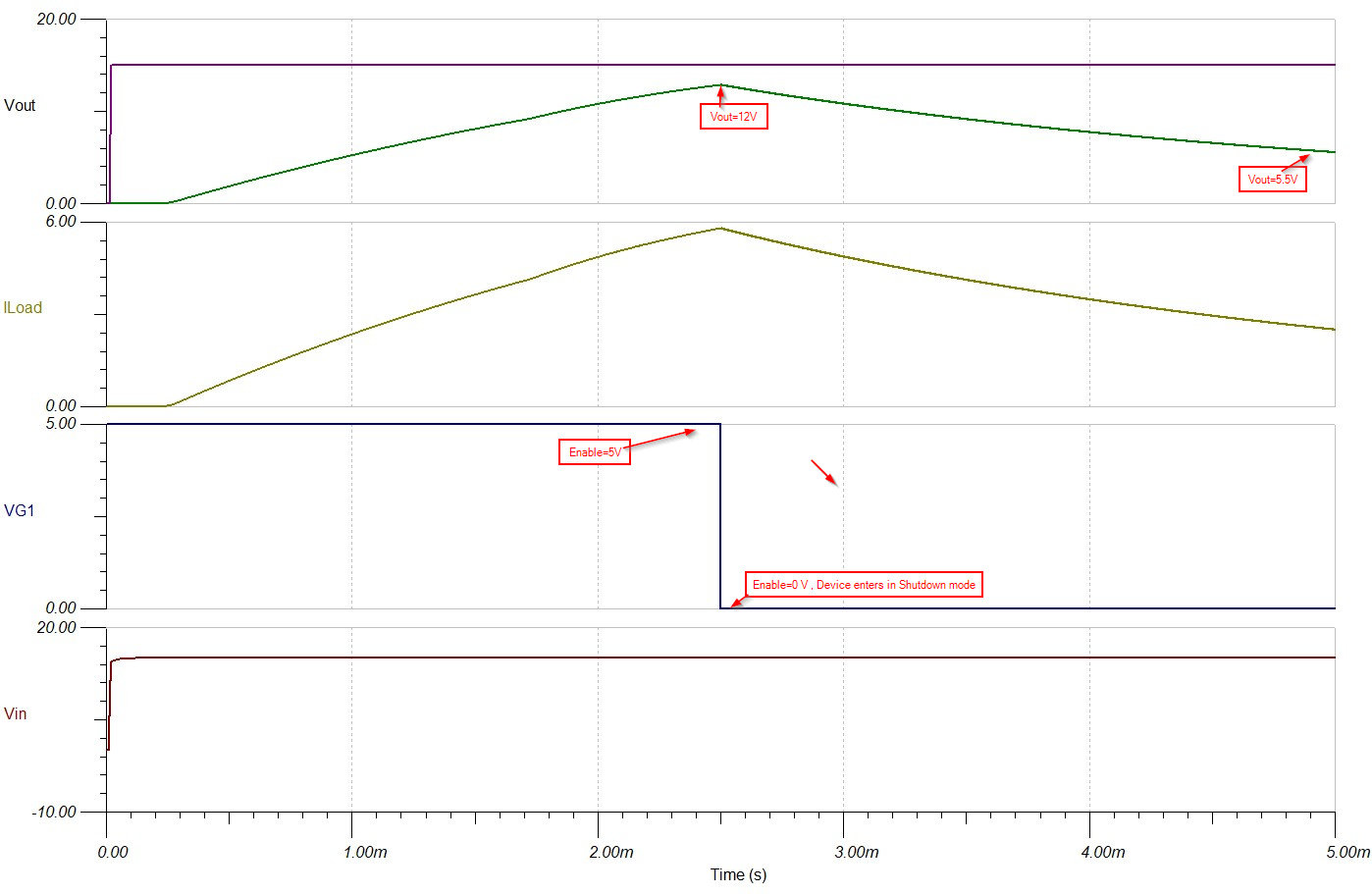
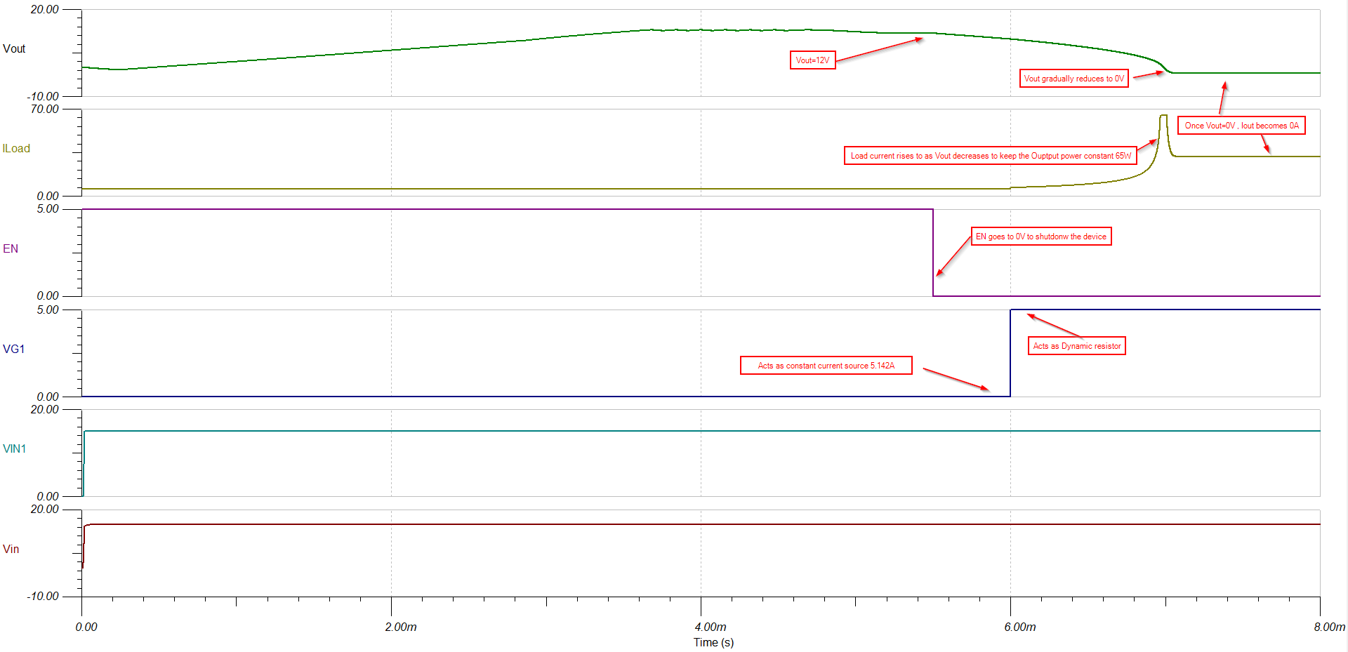
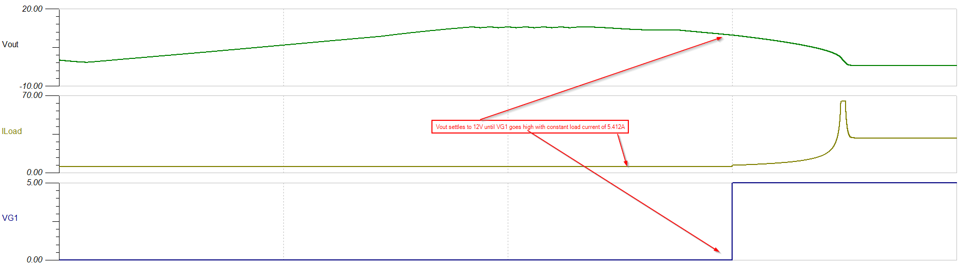
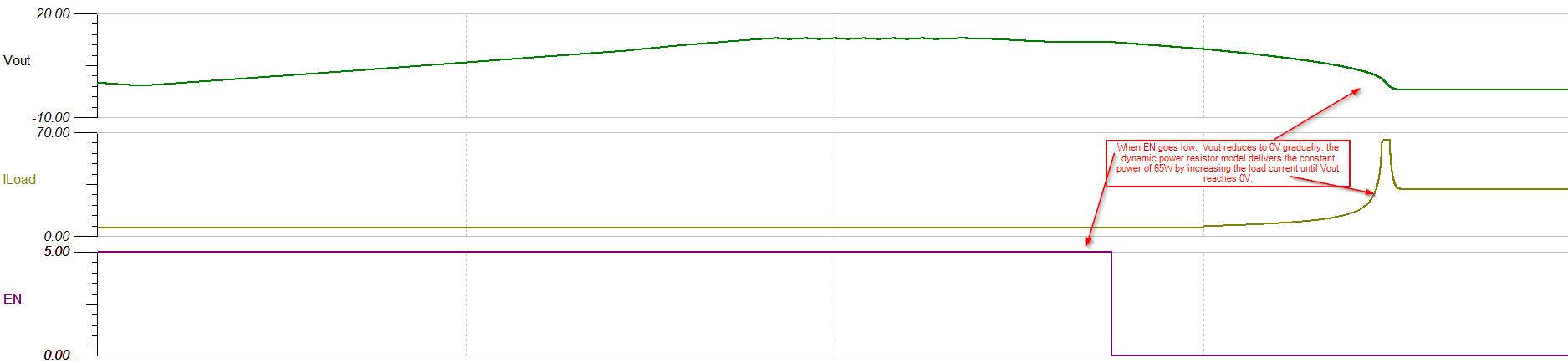
I need a way to see how much time it takes the voltage to get down to 5.5 V, when the Power stays the same (65W for our purposes) -in shutdown mode.

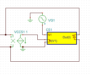
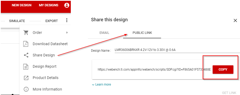
I added a switch to the WEBENCH exported design but I can't change the load resistor to be a dependent load, it doesn't compile.

Is there a way to add a Power controlled load to the LM5175-Q1 Webench exported design?

I can see that currently there is a regular resistor there because the assumption is that the output voltage is pretty much the same. 

I need my capacitors to hold the voltage for a few mseconds after shutdown and I currently don't see a possible way to simulate this option. 

Thanks! 

Anna

  • Hi Anna,

    You can export the WEBENCH design into PSpice / TINA-TI tool. Please make use of Voltage-controlled switch in the available in library and modify the circuit accordingly. The Voltage/resistor parameters of the switch can be defined as per your requirement.

    Please refer the page no.218 in the below Pspice reference guide:

    /cfs-file/__key/communityserver-discussions-components-files/234/PSpice_5F00_ReferenceguideOrCAD.pdf

    Thanks & Regards,

    Praveen

  • Hi Praveen, 

    Thanks for your reply. I already exported the design into TINA-TI and the switch itself isn't the problem. When I try to change the load to a power dependent load, the simulation doesn't compile (Tina file attached). Can you tell why I get a compilation problem?

    Thank you for your assistance, 

    Annawebench_design_6501547_3.tsc

  • Hi Anna,


    Seems like you are trying to measure the time duration between when the device enters into shutdown mode and output voltage drops below 5.5V. This can be achieved as follows.

    LM5176-Q1 enters into shutdown mode when EN/UVLO voltage is less than 0.7V. The device doesn't switch and output voltage falls down gradually from the steady-state value to zero voltage. This duration is dependent on the RC time constant. (Output capacitor and load resistor) 

    We have set the output power to 65W (Vout=12V, Iout=5.41A , RLoad= 12V/5.41A=2.21 ohm).

    The input to EN/UVLO pin is a pulse voltage source (5V for t=0-2.5ms and 0V for t>2.5ms).

    Please find the attached .tsc file:

    ./cfs-file/__key/communityserver-discussions-components-files/234/LM5175_2D00_Q1.TSC

    Result:

    Thanks & Regards,

    Praveen

  • Hi Praveen, 

    Thank you very much for this simulation. 

    I will indeed change the input as you suggested - but the problem still remains the same.

    The load resistance in the WEBENCH simulation model is a simple resistor. I need to simulate the time it takes the output to go from 12V to 5.5v, when the power remains pretty much the same after shutdown (65w).

    This is because I need the total time constant in my circuit to hold the power for a few more mseconds after shutdown.

    So, I need a constant power resistor (that will decrease with the decrease of the voltage). In your simulation you used a simple resistor as well. The problem is that when I try to replace the Rload with a constant Power resistor, the simulation doesn't converge or it provides a negative output voltage. 

    By the way, I made a mistake with the part number, and the one that we purchased is LM5176-Q1.

    I would really appreciate it if you could send me the simulation files (with LM5176-Q1) that works with a constant power load as we already explored all the options we know of. 

    Anna

  • Hi Anna,

    I have forwarded the query to product experts for further assistance. As this is a holiday season, the replies will be delayed.

    Best Regards,

    Bhushan 

  • Hi Anna,

    We have implemented the power resistor model as per your requirement. Please find the attached LM5175-Q1 TINA model below.

    /cfs-file/__key/communityserver-discussions-components-files/234/7220.LM5175_2D00_Q1.TSC

    Result:

    Please note the below points:

    1. VG1 voltage source goes high at 6ms until this time Vout settles to 12V steady-state value with a load current of 5.142A to deliver 65W power.

    2. Voltage control voltage source along with ABM acts as Dynamic resistor when VG1 goes high(5V) and it acts like constant load current source of 5.142A when VG1 is low(0V)

    3. When EN goes low, the device enters into shutdown mode and Vout reduces to 0V gradually, the dynamic power resistor model delivers the constant power of 65W by increasing the load current until Vout reaches 0V.

    Hope this will satisfy your requirement. Kindly use the same power resistor model for LM5176-Q1. Please let us know if you have any queries. 

    We would like to know the application where this power resistor will be used? Could you please provide a brief explanation?

    Thanks & Regards,

    Praveen

  • Hi Praveen, 

    I'm trying to implement your solution on a simulation file that I build according to our design. 

    First I tried to simulate the output voltage with a constant resistor and I get a sudden voltage drop as you can see below. 

    Can you identify the issue and why is happens? (Simulation file attached).

     webench_design_03_01.TSC

    I would be happy to explain to you about our application using your DC to DC via email, please let me know on which email address I can reach you guys. 

    Thank you very much for your assistance. 

    Anna

  • Hi Anna,

    Could you please share the WEBENCH design for the TINA exported file using the 'Share Design' option?

    Thanks & Regards,

    Praveen

  • Hi Praveen, 

    I modified the design after I exported it and added new macros for the transistors and the inductors and some of the capacitors in the circuit so it'll match in the best way our design. 

    This is what I exported: 

    https://webench.ti.com/appinfo/webench/scripts/SDP.cgi?ID=359359B5B685B435

    Please note that this is only the template. I made afterwards all the modifications in TINA because I wasn't able to choose some of our design parts in the WEBENCH. 

     Best regards, 

    Anna

  • Hi Anna,

    Thanks for sharing the design. We will verify the design and get back to you on this.

    Thanks & Regards,

    Praveen

  • Hi Praveen, 

    I found the mistake in the design, thanks a lot for your help, no need to verify it. 

    We have a long slow start with capacitance of CSS=100n. 

    Do you know how can I speed up the process and reach steady state faster in a transient simulation, without modifying the capacitors value? 

    In this conditions I unfortunately can't reach steady state and then simulate the shutdown, it takes too much time. 

    Thanks, 

    Anna 

  • Hi Anna,

    You can quickly reach the steady state simulation by setting the SS=1 in the model parameter and also provide the initial conditions on the capacitors like Css, Cin, Cout and inductor(if required).

    Thanks & Regards,

    Praveen

  • webench_design_good_v.tscHi Praveen, 

    The simulation provides me some unrealistic results for the power consumption of the FETs and the inductor (Tina simulation file attached). 

    I did a transient simulation for 35 msec. Can you indicate why the power consumption results are that large? 

    In addition, do you have an evaluation board for the LM5176 DC to DC that we can order? 

    Thanks, 

    Anna

  • Hi Praveen,

    I'm sorry for the multiple and confusing questions - we just found out that the large power consumption is due to a high Ciss of the MOSFETS that we chose. 

    The WEBENCH suggests this model: CSD17304Q3, but it's not suitable for us because it doesn't have automotive qualification. 

    Can you please suggest a compatible automotive MOSFET for the LM5176- Q1 DC to DC, similar to the WEBENCH suggestion, but in an automotive version? 

    Does TI have an automotive option? I couldn't find one. 

    My question on the evaluation board is still relevant, but the simulation assistance is not needed at this point, thank you.

    We would appreciate your assistance as soon as possible, this is quiet urgent for us. 

    Thank you very much, 

    Anna

  • Hi Anna,

    Currently, WEBENCH doesn't have an option to select automotive MOSFET. The queries related to the automotive MOSFET and EVM board will be answered by our product expert team. We will forward your queries to the expert team.

    Thanks & Regards,
    Praveen

  • Hello Anna,

    Please find the link to the evaluation module in the product folder of LM5176 under "Design and Development": 

    I understood the communication the way that you spoke about the LM5176-Q1, even if the headline shows LM5175-Q1.

  • Hi Anna,

    Thanks for the inquiry. TI does not have any automotive qualified FETs and we have no plans to qualify any of our FETs to automotive standards. Sorry I cannot be of more help.

  • Hi John,

    Understood, Thank you for the clarification. 

    Best regards, 

    Anna

  • Hi Praveen, 

    I saw that WEBENCH does suggests MOSFETS with similar capacitance as ours - so I don't understand why my simulation power output, when I import our automotive FETS, is very high and unrealistic (I Got 40W through one of the FETS) . When I tried the same simulation with WEBENCH suggested  MOSFETS I got a reasonable power dissipation through all 4 of them (2W maximum). Is it problematic to import a macro to a WEBENCH exported design?

    The TINA simulation file is attached, could you please assist in identifying the problem? we don't understand if the MOSFETS we chose should be replaced or if the Tina simulation doesn't work with this imported models. 

    Thank you! 

    Anna6320.webench_design_good_v.tsc

  • Hi Anna,

    The difference in power loss could be due to the below reasons. 

    1. MOSFET characteristics: MOSFET power loss is dependent on many parameters like Ciss, Coss, Crss, Qg, Qrr, Rdson. The cumulative difference between the two MOSFET parameters could lead to high power loss. Could you please let us know how did you measure the FET power loss? Kindly calculate and compare the power loss using Excel FET Loss Estimator.

    2. MOSFET TINA model: WEBENCH uses a generic template-based SPICE model for MOSFETs. While the key low-frequency characteristics like dc bias derating for Cap,  Rdson for FET etc are included in the model, the high-frequency behavior like ESL value is not very accurate in WEBENCH models. We recommend you download the vendor MOSFET SPICE models from their respective websites and perform simulations. Kindly let us know what is the source of the TINA model used for automotive MOSFET?

    Could you please confirm if you are comparing the below MOSFETs?

    Mosfet WEBENCH suggested  User  Preferred Automotive MOSFET
    M1 CSD19502Q5B IAUC100N08S5N043
    M2 CSD19502Q5B IAUC100N08S5N043
    M3 CSD16415Q5 IAUC100N04S6N028
    M4 CSD17573Q5B IAUC100N04S6N028

    Thanks & Regards,

    Praveen B

  • Hi Praveen, 

    1. I did a transient simulation of 35 msec. I measured the drain voltage and source voltage and the Id current with a probe, and then used this function: abs ((Vd-Vs)*Id). After that I did an average over 10 msec when the system reached its steady state, which produced the RMS value . This is what I did in both cases (the suggested MOSFETs and the ones we chose). 

     2. I downloaded the SPICE model directly from https://www.infineon.com/. They have some levels of the models there, I used the basic one: 

    .SUBCKT IAUC100N08S5N043_L0  drain  gate  source

    3. This is the MOSFETs WEBENCH suggested for us:

    M1- CSD18514Q5A

    M2- CSD18533Q5A

    M3- CSD16415Q5

    M4- CSD17573Q5B

    Thank you, 

    Anna

  • Hi Anna,

    Thanks for the confirmation. We will get back to you on this.

    Thanks & Regards,

    Praveen

  • Hi Anna,

    We do not think this is the correct way to measure the Mosfet power loss. But for further confirmation, our product expert will get back to you on this query.

    Thanks & Regards,
    Praveen

  • Hello Anna,

    In general power dissipation is divided in switching losses and in conduction losses. Please check these app notes for details:

    https://www.ti.com/lit/an/slyt664/slyt664.pdf

    https://www.ti.com/lit/ml/slpu004b/slpu004b.pdf

    Best regards,

    Brigitte