This thread has been locked.

If you have a related question, please click the "Ask a related question" button in the top right corner. The newly created question will be automatically linked to this question.

TINA, TPS40200 operating point

Hello,

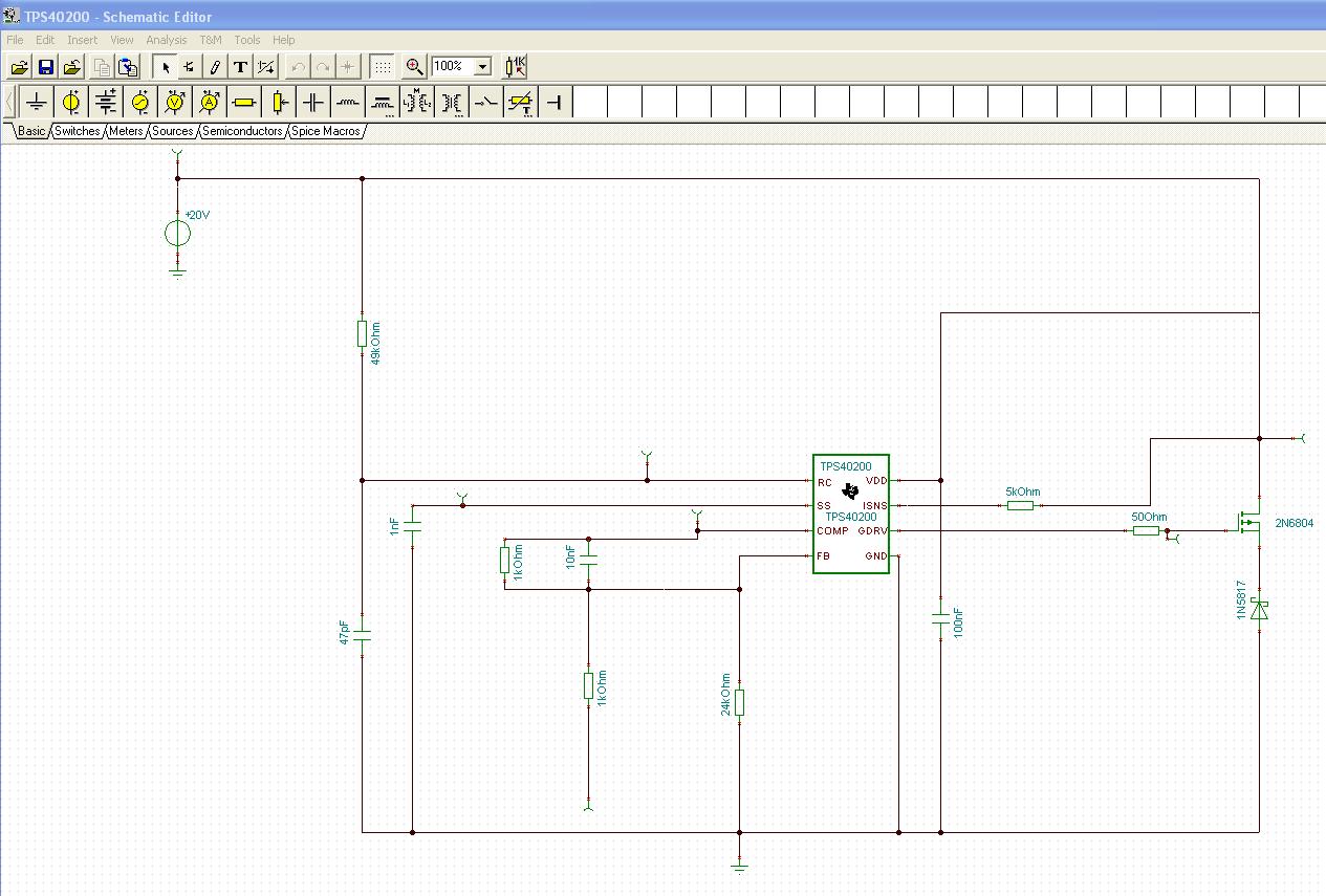
i´m doing simulations about SMPS-designing with TINA and the Controller TPS40200. I built my own circuit, similar to on of  the examples given by TI.

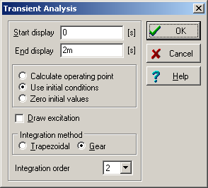
But i have still the problem, that an error occurs: Can´t find operating point. Even the TI-examples are running only in transient mode.

Have anybody an idea what parameters i´ve to change for successful simulations?


Thanks a lot and best regards

K. Reinbold

  • Hello,


    Can you attach your circuit along with this post so that we can look at the issue? I checked the circuit in the product folder and it seems to run fine. Here are the settings in that circuit.


    Best regards,

    Nikhil

  • Hello,

    at the attechment, there´s my circuit.

    I´d like to make a DC Transfer characteristic and furthermore calculating all DC results. But i´m not able to calculate the operating point and that´s way my simulation aborts.


    Best regards

    Kay


  • Hi Kay,


    The model that was provided has a hard time finding the DC operating point. If you look at the analysis section shown above, you will see that instead of calculating the DC operating point, "Use Initial Conditions" has been selected to help the circuit converge.

    I also see that you have not developed the entire circuit around the part. Can you explain to me why you are trying to find the DC Operating Point for this partial circuit and what is your end goal? 

    Best regards,

    Nikhil

  • Hi Nikhil,

    thanks for your help.

    I´m trying to simulate the DC operation point just for this particular circuit, because i´d like to know  the output-behaviour and voltages. I have another stage afterwards and this isn´t working well. My end goal is strss-analysis for every  part.


    Best regards,

    Kay


  • Hi Kay,


    In that case, I would suggest that you run the transient simulation and let the output voltage settle down. The converter will always start from 0V (since no initial conditions are specified) and hence if you do the DC analysis in the simulator, you should get 0V (which is not what you are looking for). What you really need to do it run the transient simulation till steady state and note down the circuit voltage at that point. That will be the steady state  (DC) voltage that you are looking for.


    Best regards,

    Nikhil