


I'm trying to reproduce the example LM7310 schematic using PSpice for TI simulation tool. The input voltage changes from 0 to 12V but the output stays at 0V. Please see archived simulation project as well as the example that I am trying to simulate and let me know if I am doing something wrong or if there is something wrong with the model.
Note : Pin 6 is supposed to be a N/C but the simulation is choking if I don't connect this pin to something.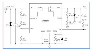 ideal_diode_af-2021-03-15T18-58.zip
