This thread has been locked.

If you have a related question, please click the "Ask a related question" button in the top right corner. The newly created question will be automatically linked to this question.

CC2652R: How to create hex files for PTM mode

Expert 1760 points
Part Number: CC2652R
Other Parts Discussed in Thread: CC2650, SYSCONFIG, , CC2651R3, CC2651P3, CC2642R, CC2640

Hello team,

I'm working on CC2652R1 MCU. (BLE SDK ver4.40.00.44)

I want to generate the PTM mode hex files for board testing.

How's it done?

I understand that for cc2650 we have the host_test example project which generates the stack and app.hex files.

But in cc2652 i read that we need to use sysconfig tool for enabling the PTM mode. I would like to know the steps to follow to generate the stack.hex and app.hex files

Thanks is advance.

Ddnr

  • Hi Ddnr,

    If you only need an image to run tests, you can directly use the host_test hexfile image stored in <SDK>\examples\rtos\CC26X2R1_LAUNCHXL\ble5stack\hexfiles\host_test_app.hex

    If your goal is rather to enable PTM on an existing project, then you should use SysConfig as you mentioned (see here). Then, when you build the project, the hex file will be generated and can be flashed on the device.

    Usually, for CC2642/CC2652R the linker produces a single hexfile (i.e. don't expect to have the stack and app in separate files).

    Bets regards,

  • Thanks Clement.

    So you mean to say host_test_app.hex is already enabled with PTM mode (and not DTM) .Is my understanding correct?

    I noticed there is an example project also for host_test in <SDK>\examples\rtos\CC26X2R1_LAUNCHXL\ble5stack\host_test. What is that used for?

  • Hi,

    So you mean to say host_test_app.hex is already enabled with PTM mode (and not DTM) .Is my understanding correct?

    Strictly speaking, this is DTM (because the host_test example is actually network processor). That being said, if your goal is to send HCI commands to the device, then you will have the exact same behavior with host_test or with simple_peripheral with PTM enabled.

    I noticed there is an example project also for host_test in <SDK>\examples\rtos\CC26X2R1_LAUNCHXL\ble5stack\host_test. What is that used for?

    This is to allow users to modify the project as they want. We have some customers using this project as development based for two-chip implementation.

    Best regards,

  • Strictly speaking, this is DTM (because the host_test example is actually network processor). That being said, if your goal is to send HCI commands to the device, then you will have the exact same behavior with host_test or with simple_peripheral with PTM enabled.

    ==> then what difference I can expect between a DTM and PTM mode?

    I read the User's guide in the link, but couldnt get the actual difference.

  • Hi,

    From a tester point of view, no difference is expected between PTM and DTM. The difference is from the developer point of view. We talk about DTM for network processors, we talk about PTM for non-network processor.

    Most of the details are provided in the related thread (CC2640: PTM CC2640 ). Quoting myself:

    Sometimes the question is asked, "What is the difference between PTM and DTM?". As described above, the test commands themselves are defined as DTM and accessed via HCI network processor (e.g., Host_Test). PTM is simply a means to access DTM commands in non-network processor configuration. Entering PTM (e.g., via a pogo pin driving a GPIO) exposes these same DTM commands over a UART interface to a single-device (non-network processor) firmware configuration.

    I hope it is clearer.

    Regards,

  • Yes it is much clearer now.

    Our actual MCU is based on CC2651R3 5x5 package. And when i tried flashing this host_test_app.hex file, it is not working for me. (obviously it won't work as the uart pins might be changed).

    May I know what pins are used in the CC2651R3 5x5 package and is it the same as configured in the host_test_app.hex available.?

  • Hi,

    May I ask you which image you attempt to flash on the CC2651R3? The image compiled for CC2652R are not expected to work on the CC2652R device.

    For CC2651R3, we recommend to use the projects we provide for CC2651P3. Then you need to port the project to the CC2651R3. We have detailed the steps to port the project here.

    With that said, SDK 5.20 does not provide the host_test example for CC2651P3. As a consequence I would recommend to use the simple_peripheral example and enable PTM as discuss earlier.

    Best regards,

  • I have tried to flash host_test_app.hex available for CC26X2R1_LAUNCHXL in the path \ti\simplelink_cc13x2_26x2_sdk_4_40_00_44\examples\rtos\CC26X2R1_LAUNCHXL\ble5stack\hexfiles as I couldn't find anything similar to CC2651R3 5x5 in examples.

    (BLE SDK ver4.40.00.44) is the sdk version I'm using right now.

  • Hi,

    Thank you for telling me.

    As mentioned before, this will not work. Please follow the suggestion made in my previous message.

    Best regards,

  • Hi Clement,

    Thanks for clarifying.

    But I see LP_CC2651P3, is the same package as CC2651R3 with 5x5 package? May I know the UART pin configurations in both CC2651P3 and CC2651R3 please?

  • Hi,

    Actually, the devices in the CC26xx/CC13xx family allow to use pretty much any pin for any peripheral. SysConfig can be leveraged to associate the pins you want to the peripheral.

    By default, on our LP_CC2651P3 the XDS110 UART is connected to DIO13 (TX) and DIO12 (RX).

    If it was not clear, the CC2651P3 and CC2651R3 devices are not binary compatible.

    Best regards,

  • Hello Clement,

    My Colleague has got an information from TI, that the PTM is same for CC2652 and CC2651.

    I'm a bit confused now, because in that case why hex file for cc2652 (host_test_app.hex) wont work in cc2651r3?

  • Hi,

    My Colleague has got an information from TI, that the PTM is same for CC2652 and CC2651

    This is true. Have you got this information through an E2E thread? If yes, could you please point me to it?

    why hex file for cc2652 (host_test_app.hex) wont work in cc2651r3?

    Even if PTM works the same way on CC2652R and CC2651R3, the two devices have significant differences (especially at Core and ROM levels) preventing you to run the same binary on both devices.

    Best regards,

  • No, the information received is through mail by TI FAE and not through a forum.

  • No, the information received is through mail by TI FAE and not through a forum.

    Thank you for telling me. I just wanted to be sure I have the whole picture and not missing any piece of information Slight smile

    Regards,

  • Hi Clement,

    I have gone through this link as you mentioned

    For CC2651R3, we recommend to use the projects we provide for CC2651P3. Then you need to port the project to the CC2651R3. We have detailed the steps to port the project here.

    https://dev.ti.com/tirex/content/simplelink_cc13x2_26x2_sdk_5_20_00_52/docs/ble5stack/ble_user_guide/html/cc13x2_26x2/software-on-cc13x1x-26x1x.html#running-software-examples-on-the-litedevice

    But have few doubts:

    1. It is mentioned "The CC13x1x or CC26x1x is pin compatible with their respective CC13x2x1 or CC26x2x1 " means the pin config can be used as it is ?+

    2. Also since LP_CC2651P3.syscfg.json is available and also P3 is functionally compatible as R3 why should we go with renaming  CC26X2R1_LAUNCHXL.syscfg.json instead of directly renaming P3?

    3. May I know what is the differnce between CC2651P3 and CC2651R3 ?

  • Hi,

    1- Yes

    2- I guess either options are fine. However I have not tested the option you are suggesting.

    3- The P stands for "Power Amplifier". In other words, the P devices can transmit up to [EDIT: CC2651P3 is limited to +10dBm]+20dBm (+5dBm for R devices). Please see this blog post for additional details.

    Best regards,

  • I have some doubts here, it is mentioned as :

    1. Marked as green, i found the .json file in the path. Where I should paste this file after copying.

    (When I create a project, the project folder created doesn't include any .json file). So is it required to copy this file from sdk and paste it in any project path or directly I can change the name in sdk itself ?

    2. Marked in RED, where i should edit the SysConfig file as I couldn't find the file in the project created?

    3. We are using CC2651R3 custom board for testing and not LP. So are the steps work with the custom board also?

  • Hi,

    Thank you for the feedback on the documentation. I will make sure this get improved for our next release.

    1- The .json file should be pasted in the same location.

    2- The "SysConfig file" is a file ending with .syscfg

    3- Yes. Additional changes (due to the design of your custom board) may be required.

    Best regards,

  • Hi Clement,

    Thanks for reverting.

    1. Please clarify the same location meant -> is it the same sdk location or in the project path which is newly created.?

    2. I know about the sysConfig file. But when I created the project, in the project path I couldn't find the .syscfg file. Only Settings.Release folder and some files related to IAR workspace is available. In that case should I copy the .syscfg and other folders like Startup, Application into the project path ?

    Thanks.

  • Hi,

    1- The same location means <SDK_DIR>\source\ti\boards\.meta

    2- Have you imported the CC2651P3 in IAR? Could you please provide a screenshot of the project when opened with IAR?

    Regards,

  • Thanks.

    Yes, here is the screeshot. But I copied the Application, Startup folders, .syscfg to build, otherwise it is throwing error that file is missing.

    Also I noticed the pka.h file error due to the particular file which is reffered, is missing in the device family folder of \ti\simplelink_cc13x2_26x2_sdk_5_20_00_52\source\ti\devices\cc13x1_cc26x1\driverlib

  • Please update me asap on further steps.

    Thanks

  • Hi,

    Something went wrong with the project import.I would recommend to restart from the beginning, following the quick start guide. Alternatively, you may want to use CCS - which according to me slightly easier to handle.

    Once you have imported the project, make sure it builds properly before going any further.

    Generally speaking, copying the .syscfg file from a different project does not work as it leads the tool-chain to use some driver files for CC2642R (e.g. ECDHCC26X2.h is not compatible with CC26x1 devices).

    Best regards,

  • Hi Clement,

    I could able to import the project and build successfully ( I have imported the project -> \ti\simplelink_cc13x2_26x2_sdk_5_20_00_52\examples\rtos\LP_CC2651P3\ble5stack\simple_peripheral). I have gone as per the steps mentioned and enable the PTM and built the code.

    For CC2651R3, we recommend to use the projects we provide for CC2651P3. Then you need to port the project to the CC2651R3. We have detailed the steps to port the project here.

    With that said, SDK 5.20 does not provide the host_test example for CC2651P3. As a consequence I would recommend to use the simple_peripheral example and enable PTM as discuss earlier.

    We are currently using the CC2651R3 MCU based custom board and the UART pin is DIO2 and DIO3. And the UART pin is also the same in the imported project also. But still the hex file build is not working with our custom board.

    What other Additional changes (specified in previous message) should be taken care to make it work?

    Thanks in advance.

  • Hi,

    Good to see it's moving in the right direction.

    Could you specify what you mean by not working? Do you manage to flash the hex file on the device?

    If yes, then I would recommend to use CCS debugger to try to identify the issue. You can find more details on our debugging guide.

    Keep us updated.

    Best regards,

  • Not working means the UART is not responding.

    Yes I flashed the hex file. OK.

    I understood the issue, we are using a custom board based on RKP package (5x5) 40pins. But in the sysconfig tool I'm not able to find the particular package and is default set to RKZ package. In this case how can I proceed?

    or Could you please update the sdk with RKP (5x5) package? Or is there any other way around.

  • Hello Clement,

    Could you please support us on priority here.

    Thanks.

  • Hi,

    Could you please explain why you think the issue is due to the specific package you are using? Do you see any specific infinite loop being executed?

    Other than that, do you see the device advertising? (you could use a phone with a Bluetooth LE app like LightBlue to verify this).

    Best regards,

  • Hi Clement,

    Yes. the package we are using is RKP. (5x5 package with 40pins). I got the info from my colleague who is responsible for hardware. ( And in the sysConfig tool by default RKZ package is choosen as we dont have option to choose from multiple packages 
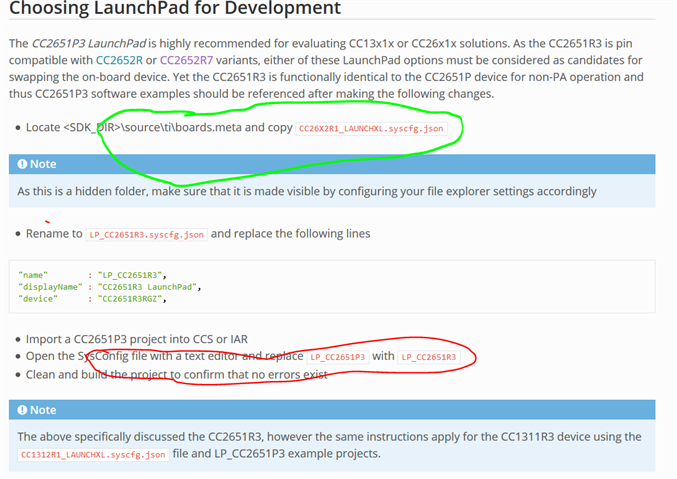
). Please see the screenshot.
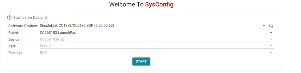
  • Hi,

    I agree. But as long as you are not using non-existing pins, you should be fine.

    Do you see the device getting caught in some sort of infinite loop? Do you see the device advertising?

    Best regards,

  • Hi Clement,

    It was not advertising also. So i tried debugging it. And I got this error ->

     Error[Lp011]: section placement failed   

    unable to allocate space for sections/blocks with a total estimated minimum size of 0xb490 bytes (max align 0x80) in <[0x2000'00d8-0x2000'7fff]> (total uncommitted space 0x7b28).

  • Hi,

    And I got this error ->

     Error[Lp011]: section placement failed   

    unable to allocate space for sections/blocks with a total estimated minimum size of 0xb490 bytes (max align 0x80) in <[0x2000'00d8-0x2000'7fff]> (total uncommitted space 0x7b28).

    Is it correct understanding you are getting this error at build time?

    Best regards,

  • Yes, I'm getting this error when I build in debug mode. In Release mode I'm not getting error.

  • Hi,

    That error message means that you're running out of memory. If I understand your setup correctly (listed below) then this should not happen. SimplePeripheral with a single UART enabled should not use that much memory.

    Hardware: Custom Board with CC2651R3 device with RKP Package

    Software: Simple_Peripheral_LP_CC2651P3_tirtos_ccs completely unmodified except for a UART added on pins 2 and 3.

    Is this correct?

  • Hi Nathan,

    Yes, the hardware and software configs are correct.

    Do you see the device getting caught in some sort of infinite loop? Do you see the device advertising?

    I can see the advertising when the PTM is not enabled. When I enable the PTM mode, then the control is getting caught in NPITask_transportRXCallBack() infinite loop.

  • Great. I have mimicked your setup on launchpads, and I'm finding that it errors out too. I'm not sure if this is the result of the setup or an actual bug though. I will review with my team in the morning and proceed from there. Thank you for your patience.

  • Hi,

    It would be helpful if you can reach me back with solution why after enabling PTM , the control is getting caught in a loop. I'm unable proceed.

    Thanks.

  • Hi Clement,

    Please see my comments below , what I observed yesterday while testing.

    Do you see the device getting caught in some sort of infinite loop? Do you see the device advertising?

    I can see the advertising when the PTM is not enabled. When I enable the PTM mode, then the control is getting caught in NPITask_transportRXCallBack() infinite loop.

  • Hi,

    Your results are actually encouraging. It is good to see you manage to get the device advertising and enter PTM mode. On the top of that it seems the device does see something on its UART line.

    Do you mean you are blocked in the "for(;;);" loop of the following function?

    static void NPITask_transportRXCallBack(int size)
    {
        // Check for overflow of RxBuf:
        // If the buffer has overflowed there is no way to safely recover. All
        // received bytes can be packet fragments so if a packet fragment is lost
        // the frame parser behavior becomes undefined. The only way to prevent
        // RxBuf overflow is to enable NPI_FLOW_CTRL.
        //
        // If NPI_FLOW_CTRL is not enabled then there is no way to for slave to
        // control the master transfer rate. With NPI_FLOW_CTRL the slave has SRDY
        // to use as a software flow control mechanism.
        // When using NPI_FLOW_CTRL make sure to increase NPI_TL_BUF_SIZE
        // to suit the NPI frame length that is expected to be received.
        if ( size < NPIRxBuf_GetRxBufAvail() )
        {
            NPIRxBuf_Read(size);
    #ifdef ICALL_EVENTS
            Event_post(syncEvent, NPITASK_TRANSPORT_RX_EVENT);
    #else //!ICALL_EVENTS
            TRANSPORT_RX_ISR_EVENT_FLAG = NPITASK_TRANSPORT_RX_EVENT;
            Semaphore_post(appSem);
    #endif //ICALL_EVENTS
        }
        else
        {
            // Trap here for pending buffer overflow. If NPI_FLOW_CTRL is
            // enabled, increase size of RxBuf to handle larger frames from host.
            for(;;);
        }
    }

    If yes, have you reviewed the comments?

    Do you use Flow Control? What is the value for NPI_TL_BUF_SIZE?

    Best regards,

  • Hi Clement,

    Thanks for getting back. I have not enabled the Flow Control. Only PTM is enabled.

    Also one more observation is sometimes control is going to Error_policySpin and is getting blocked there.

    /*
     *  ======== Error_policySpin ========
     */
    /* REQ_TAG(SYSBIOS-854) */
    /* LCOV_EXCL_START */
    Void Error_policySpin(Error_Block *eb, Types_ModuleId mod, CString file,
        Int line, Error_Id id, IArg arg1, IArg arg2)
    {
    /* LCOV_EXCL_STOP */
        for(;;) {
        }
    }

    May I know in what scenario it calls this error function?

  • Hi Clement,

    Adding to the above comment, I kept breakpoint and observed once the

    GAP_DeviceInit(GAP_PROFILE_PERIPHERAL, selfEntity, addrMode, &pRandomAddress);

    is called, the control is not coming out of this function and when I pause the execution, it is moving to Error_policySpin() function.

    What could be the reason of Gap not getting initialised properly or getting hang.?

    Thanks.

  • Hi,

    Generally speaking, when the program is stopped by a break-point, the timing get significantly disturbed and the Bluetooth LE stack may crash.

    With that being said, I would like to focus on the issue leading to an infinite loop in NPITask_transportRXCallBack().

    Could you please tell us what is the value of NPI_TL_BUF_SIZE and see if increasing its value could help?

    Thanks and regards,

  • Hi,

    The NPI_TL_BUF_SIZE is defined as:


    #if defined( CC26X2 ) || defined( CC13X2 ) || defined( CC13X2P )
      #ifndef NPI_TL_BUF_SIZE
        #define NPI_TL_BUF_SIZE         1680
      #endif
    #else // CC26XX_R2 || CC1350LP_7XD ... 
      #ifndef NPI_TL_BUF_SIZE
        #define NPI_TL_BUF_SIZE         330
      #endif
    #endif // CC26X2 || CC13X2

    I couldn't find the device family for CC2651R3/P3 here? So I think it is 330, I increased it to 1680 and can't find any difference.

  • Hello Clement,

    Did I answer your question, about NPI_TL_BUF_SIZE ?

  • Hi,

    Did I answer your question, about NPI_TL_BUF_SIZE ?

    I guess I have the information I needed but I don't understand why we would run into this overflow.

    May I ask you if you are sending UART commands to the device?

    If yes, could you please specify

    • which commands are sent?
    • which tool is used to send the commands? (BTool, a serial terminal, etc.)
    • how is the UART configuration? (baudrate, stop bit, etc.)

    Best regards,

  • Currently I'm not sending any commands. That is why even I'm not understanding why is it getting inside the else case loop. 

    Firstly the control is coming to if condition and after few iterations i think it is getting inside the else case.

    Great. I have mimicked your setup on launchpads, and I'm finding that it errors out too. I'm not sure if this is the result of the setup or an actual bug though. I will review with my team in the morning and proceed from there. Thank you for your patience.

    Also I'm adding the sysconfig screenshot here just to check if my ptm enabling is correct.

  • Hi,

    The screenshot provided looks fine to me. I have asked Nathan to comment if he spots anything.

    To continue the debug, I would recommend to probe the UART lines to see if you can spot some noise. If not UART operation occurs, both TX and RX lines should be help high.

    After this, I would recommend to use BTool in order to send the PTM commands to the device. (BTool is provided within the SDK in <SDK>\tools\ble5stack\btool). Here again, I would recommend to send a command (e.g. HCI_Reset command)

    Keep us updated,

    Best regards,

  • Hi Clement,

    Here is what I observed->

    • I have two HCI SW to communicate with BT modules. Both programs work with my cc2640 (previous module). One is called BlueC  Another one is HCI Tester 2. Both programs communicate via UART.
    • I set the COM port to à Baud Rate: 115200 / Parity: NONE / Data Bits:8 / Stop Bits: One
    • I did set the HCI_Reset command. The issue is that I cannot establish UART communication.
    • With CC2640, when I send the command to set the RF channel to 2450 MHz (01 1E 20 03 18 25 00) and then the end_test command  01 1F 20 00. I received the response for both the commands.
    • With CC2651R3, there is no echo from the MCU and nothing happened on RF signal.

     Thanks.

  • Hi,

    Thank you for these details.

    Have you tried to probe the UART line? I think this is what needs to be done now in order to understand why the UART Rx Buffer gets overflowed.

    Best regards,