This thread has been locked.

If you have a related question, please click the "Ask a related question" button in the top right corner. The newly created question will be automatically linked to this question.

CC2640R2F: SPI miso pin state is 2.5 volts while communication is not going over SPI.

Part Number: CC2640R2F

Hi

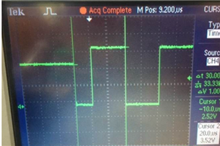
I am working on CC2640R2F and using the SPI driver configured as master. While communication is going on the pin states are fine, but while communication is not going on the MISO pin is neither high nor low but is in a floating state (2.5 v)

I have attached the DSO trace. 

What can be the impact of this?

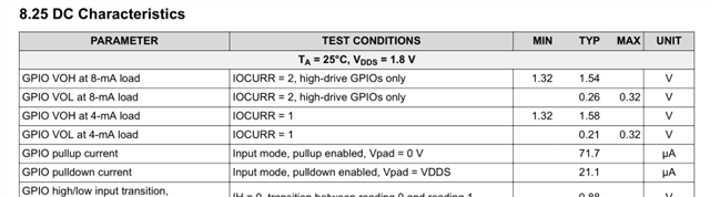
Any method to fix the state of the MISO pin to either high or low when SPI is in an idle state?

Regards

Sudhanshu

  • Sudhanshu,

    From what I understand, the CC2640R2F is configured as master, right? If so, the MISO pin is an input to the CC2640R2F and therefore high impedance, thus very influenced by the external circuitry connected to it.

    I would definitely check the other devices tied to this pin, as well as any passive devices (resistors, capacitors) that may be bringing this line up.

    Hope this helps,

    Rafael

  • Hi

    I agree with you.

    An external pullup to 3.3v is connected to the MISO pin. When I disconnect this pull-up resistor MISO pin goes to level 0.

    But when this pullup is connected then the voltage level shifts to 2.5 volts, ideally after connecting the pull-up voltage level should be 3.3v

    Is it so that my MISO pin is internally sinking some current when I connect the pull-up resistor?

    If yes then how to rectify this?

    Regards

    Sudhanshu

  • Sudhanshu,

    In general input pins have a very small leakage but, in the case of SPI, they have their internal pulldown enabled by default in a typical spislave project. Check the file <CC2640R2_LAUNCHXL.c>

    The datasheet mentions that a typical DC current of the pulldown is about 21µA for VDDS applied to the pin. 

    Therefore, if you haven't changed the default setting on the device and you are using a pullup resistor lower than the pulldown (perhaps ~47 kΩ ?), it is expected to have a voltage if the master output pin is tri-state.

    You can simply disable the pulldown on the pin driver configuration and rely on the external resistor.

    Hope this helps,

    Rafael

  • Hi

    I understood your point. I already configured the pin as input pullup in the boardgpioinit[] table then also the voltage is ~2.6v

    What I observed is that if I don't initialize my SPI driver then the pin state is 3.3v but after SPI initialization voltage shifts to 2.6v i.e. SPI initialization overwrites the MISO pin configuration.

    Is it so that SpiInit( ) function configures the SPI MISO pin as input pull down?

    Because my pull-up resistor is 10kohm, so if the MISO pin is input pulldown so a voltage divider will make the voltage level 2.6v as you explained.

    What can be done within the SPI initialization to configure the MISO pin to input pullup after initializing the SPI driver?

    Regards

    Sudhanshu

  • Sudhanshu,

    That is interesting and I don't know the answer to this. I will consult with some colleagues and test this next week.

    Regards,

    Rafael