This thread has been locked.

If you have a related question, please click the "Ask a related question" button in the top right corner. The newly created question will be automatically linked to this question.

CC2564: CC2564BRVMR

Part Number: CC2564
CC2564BRVMR module(BT) gives error reply when MCU tries to create connections.
 
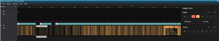
I tried to detect the BT pins logic using Logic analyzer and scope, such as TX/RX pins.
MCU sends the correct command data to BT, but BT replied seems crazy data.
 
This capture shows only the BT TX pin reply(0xFF), I assume the BT works un-normally.
 
 
You maybe ask "Are you sure you sent the correct data?"
I am pretty sure, because I can see the correct data using logic analyzer and I also use the BT TX_DBG pin to see thee correct configurations
 
Here is the TI Logger shows as blow tables
 
164 ZKD1(Assembly lot code)
uart_hci parameters: UartDIV=3, OS=23, SP=0, MoB=10
temperature sensing: temp 20, read 0x23, vbe 0x299597d, slope 0x1f2f0
Temperature region = 6
In lc_rf_init_periodic_calibration
synch event REG received, module RF_CALIBRATION, msi 0
synch cmd start instance, module RF_CALIBRATION, msi: 0
synch cmd return event STARTED,module RF_CALIBRATION
ORCA Platform
Process type: Weak
Chip revision: 6
Detected Clock = 26000000 Hz
Ref Clock = 26000000 Hz
XTAL wakeup mode  is disabled
Ref Clock is valid for PLL
PLL Clock Output is OK
PLL Clock Out = 40000000 Hz
Clock Working mode: PLL Mode
ARM Clock = 40000000 Hz, Slow Clock: External
OCP Clock = 8000000 Hz
UART HCI baudrate = 115200
Gemini type Soft Gemini
lm_lc_get_local_features
lm_lc_set_brcst_retran
lm_lc_self_test_run_init_tests
Self Test passed
I2C doesn't exist !
lm_lc_get_local_bd_addr
Software version - 7.0.16
Deactivating timer: init
lm_lc_rf_periodic_calibration
Calibration started. Vector=0x1, 0x0
PHY FW Version 3.27
random 0x8fca 0x2b78
random 0x1eb8 0x475d
random 0xe63a 0x2728
random 0xb09e 0x1e9c
random 0x6b41 0xa9e6
lm_lc_generate_rand
lm_lc_generate_rand
synch event FINISH received, module RF_CALIBRATION, msi 0
lm_lc_generate_rand
lm_lc_generate_rand
Transport detection: UART detected
first byte recevied 1
Disable FLIGHT MODE - Enable TX calibration
Uart Active Protocol: H4 PROTOCOL
hcic_process_hci_commands: HCI_RESET (Group 3 Opcode 0x3)
lm_lc_gemini_coex_notify_scan_status
HCI_Reset Completed
hcic_get_num_of_host_commands. Total free = 3, Reported to host = 1
HCI Send Event: HCI_COMMAND_COMPLETE_EVT
uart_hci parameters: UartDIV=3, OS=23, SP=0, MoB=10
temperature sensing: temp 23, read 0x22, vbe 0x2934cb1, slope 0x1f2f0
Temperature region = 6
In lc_rf_init_periodic_calibration
synch event REG received, module RF_CALIBRATION, msi 0
synch cmd start instance, module RF_CALIBRATION, msi: 0
synch cmd return event STARTED,module RF_CALIBRATION
 
 
I donot know what is the difference between Process type: Weak and Process type: Nominal.
But we can see BT accepted the command and gives the reply
HCI Send Event: HCI_COMMAND_COMPLETE_EVT
 
BT send the wrong data from the TX pin.
 
 
My questions:
1. How to see what kinds of raw data the BT sending or receiving using the TI Logger or other SW tools?
2. How to confirm what is the reason cause this problem? It is so weird about this BT.
 
We have ZT9Y, ZKD1 and ZKD2 BT modules.(Assembly lot code)

ZT9Y can work normally, but ZKD1 happens this issue.


  • BT TX logic capture is missing, added here.

  • Hi TI experts,

    I find new: Disabling UART HW flow impacts this.

    But I have one more new question:

    What is the process when MCU calls BSC_Initialize() interface? Could you share more information about BSC_Initialize or HCI process flow?

    You know, BT can review the correct data(op code 03) from MCU when disabling the uart hw flow setting. I am not clear why the BT sends the wrong data to MCU in this case.

  • Hey Carlos,

    I'll follow up here later this week.

    Thanks,
    Jacob

  • Hi Carlos,

    To answer your above questions:

    1. You can view the firmware / HCI communication from our device by probing the TX_DBG pin on the CC2564 device. You do need a UART to USB converter to handle the voltage translation. You can read more about it here.

    2.  To answer this question, can you share the MCU and supported Bluetooth stack you are using? I'm wondering if there is an inconsistency.

    What is the process when MCU calls BSC_Initialize() interface? Could you share more information about BSC_Initialize or HCI process flow?

    I cannot share all of this information as this is a function from our source code. To put it briefly, the function checks that the HCI driver information passed in is valid. Next, it checks the Bluetooth BD address. Then, it initializes the layers and profiles.

    Did you say you receive correct data from the MCU if you disable flow control?

    Thanks,
    Jacob 

  • 1. I think it could not resolve my questions

    2. I am using ST(stm32f405rgt6) and GD(gd32f450vkt6) mcus in this case.

    The BT stack is bluetopia with BT 4.2 software version and BT 1.2 hardware version.

    I just would like to know the process/flow, no need your source codes.

    3. I am pretty sure that BT receives correct data from the MCU if I disable flow control, please see the tables I uploaded in the first commit question

    ```

    hcic_process_hci_commands: HCI_RESET (Group 3 Opcode 0x3)
    lm_lc_gemini_coex_notify_scan_status
    HCI_Reset Completed

    ```

  • Logger somehow could not show what kind of raw data it received. But it shows it accepted the mcu command data with the reset command

  • Hi Carlos,

    The logger program lists the firmware and protocol transactions from the BT controller. I think you can view the raw data received over the RX line (it looks like you did that above).  

    Is your question still: why is the BT controller responding with 0xFF? If so, I think it would be helpful to take logs of a simple use case - running the "Inquiry" command with one of our STM32 demo applications. Can you take logs running "Inquiry" from SPPDemo? 

    And just to be sure, you are using the CC256XSTBTBLESW stack, correct? This is a BT 4.0 stack which is compatible with the CC2564B. For the 4.2 stack, you need a CC2564C. 

    Thanks,
    Jacob

  • ```


    /* Bluetooth Protocol Stack Core Support . */
    #define BTPS_VERSION_MAJOR_CORE_SUPPORT 4

    /* Bluetooth Protocol Stack Core Support . */
    #define BTPS_VERSION_MINOR_CORE_SUPPORT 0


    /* Bluetooth Protocol Stack Major Version Release Numbers. */
    #ifndef BTPS_VERSION_MAJOR_VERSION_NUMBER
    #define BTPS_VERSION_MAJOR_VERSION_NUMBER 2
    #endif

    /* Bluetooth Protocol Stack Minor Version Release Numbers. */
    #ifndef BTPS_VERSION_MINOR_VERSION_NUMBER
    #define BTPS_VERSION_MINOR_VERSION_NUMBER 1
    #endif


    /* Customer Major Version Release Numbers. */
    #ifndef PLATFORM_MAJOR_VERSION_NUMBER
    #define PLATFORM_MAJOR_VERSION_NUMBER 1
    #endif

    /* Bluetooth Protocol Stack Minor Version Release Numbers. */
    #ifndef PLATFORM_MINOR_VERSION_NUMBER
    #define PLATFORM_MINOR_VERSION_NUMBER 1
    #endif

    ```

    ah, maybe some information was explained not good, but I paste there here.

    The code was ported before many year. I just noticed this issue recently.

    It is hard to test the original code based on GD mcus.

  • HI Carlos,

    I'll follow up next week.

    Thanks,
    Jacob

  • BTW, I find another BT module hardware issue, please also check the ERROR CODE, I dont know how to trace this issue.

    Uart Active Protocol: H4 PROTOCOL
    HW_ERR, 276, 11

    TL-, H4 Protocol, h4_abort_receive() - error_code = 11

    1296 11/25/21 10:22:29.286   -551:13:53.528 0x00000028 0x00000028 <---- HCI_Hardware_Error_Event
    1297 11/25/21 10:22:29.287   -551:13:53.527 uart_hci parameters: UartDIV=3, OS=23, SP=0, MoB=10
    1298 11/25/21 10:22:29.287   -551:13:53.527 temperature sensing: temp 34, read 0x22, vbe 0x2934cb1, slope 0x1e0a7
    1299 11/25/21 10:22:29.287   -551:13:53.527 Temperature region = 7
    1300 11/25/21 10:22:29.287   -551:13:53.527 In lc_rf_init_periodic_calibration
    1301 11/25/21 10:22:29.287   -551:13:53.527 synch event REG received, module RF_CALIBRATION, msi 0
    1302 11/25/21 10:22:29.287   -551:13:53.527 synch cmd start instance, module RF_CALIBRATION, msi: 0
    1303 11/25/21 10:22:29.287   -551:13:53.527 synch cmd return event STARTED,module RF_CALIBRATION
    1304 11/25/21 10:22:29.287   -551:13:53.527 ORCA Platform
    1305 11/25/21 10:22:29.287   -551:13:53.527 Process type: Nominal
    1306 11/25/21 10:22:29.287   -551:13:53.527 Chip revision: 6
    1307 11/25/21 10:22:29.287   -551:13:53.527 Detected Clock = 26000000 Hz
    1308 11/25/21 10:22:29.287   -551:13:53.527 Ref Clock = 26000000 Hz
    1309 11/25/21 10:22:29.287   -551:13:53.527 XTAL wakeup mode  is disabled
    1310 11/25/21 10:22:29.287   -551:13:53.527 Ref Clock is valid for PLL
    1311 11/25/21 10:22:29.287   -551:13:53.527 PLL Clock Output is OK
    1312 11/25/21 10:22:29.287   -551:13:53.527 PLL Clock Out = 40000000 Hz
    1313 11/25/21 10:22:29.287   -551:13:53.527 Clock Working mode: PLL Mode
    1314 11/25/21 10:22:29.287   -551:13:53.527 ARM Clock = 40000000 Hz, Slow Clock: External
    1315 11/25/21 10:22:29.287   -551:13:53.527 OCP Clock = 8000000 Hz
    1316 11/25/21 10:22:29.287   -551:13:53.527 UART HCI baudrate = 115200
    1317 11/25/21 10:22:29.287   -551:13:53.527 Gemini type Soft Gemini
    1318 11/25/21 10:22:29.287   -551:13:53.527 lm_lc_get_local_features
    1319 11/25/21 10:22:29.287   -551:13:53.527 lm_lc_set_brcst_retran
    1320 11/25/21 10:22:29.287   -551:13:53.527 lm_lc_self_test_run_init_tests
    1321 11/25/21 10:22:29.287   -551:13:53.527 Self Test passed
    1322 11/25/21 10:22:29.287   -551:13:53.527 I2C doesn't exist !
    1323 11/25/21 10:22:29.287   -551:13:53.527 lm_lc_get_local_bd_addr
    1324 11/25/21 10:22:29.287   -551:13:53.527 Software version - 7.0.16
    1325 11/25/21 10:22:29.287   -551:13:53.527 Transport Detection: eSPI or UART
    1326 11/25/21 10:22:29.287   -551:13:53.527 Deactivating timer: init
    1327 11/25/21 10:22:29.287   -551:13:53.527 Transport detection: UART detected
    1328 11/25/21 10:22:29.287   -551:13:53.527 first byte recevied 6
    1329 11/25/21 10:22:29.287   -551:13:53.527 Uart Active Protocol: H4 PROTOCOL
    1330 11/25/21 10:22:29.287   -551:13:53.527 HW_ERR, 276, 11
    1331 11/25/21 10:22:29.287   -551:13:53.527 TL-, H4 Protocol, h4_abort_receive() - error_code = 11
    1332 11/25/21 10:22:29.287   -551:13:53.527 lm_lc_rf_periodic_calibration
    1333 11/25/21 10:22:29.287   -551:13:53.527 HCI Send Event: HCI_HARDWARE_ERROR_EVT
    1334 11/25/21 10:22:29.287   -551:13:53.527 Calibration started. Vector=0x1, 0x0
    1335 11/25/21 10:22:29.287   -551:13:53.527 PHY FW Version 3.27
    1336 11/25/21 10:22:29.287   -551:13:53.527 random 0xeba3 0xa413
    1337 11/25/21 10:22:29.287   -551:13:53.527 random 0x4c72 0xa6bb
    1338 11/25/21 10:22:29.287   -551:13:53.527 random 0xc538 0xc5d7
    1339 11/25/21 10:22:29.287   -551:13:53.527 random 0xeecb 0x7f4
    1340 11/25/21 10:22:29.287   -551:13:53.527 random 0xf72c 0x24ba
    1341 11/25/21 10:22:29.287   -551:13:53.527 lm_lc_generate_rand
    1342 11/25/21 10:22:29.287   -551:13:53.527 lm_lc_generate_rand
    1343 11/25/21 10:22:29.287   -551:13:53.527 synch event FINISH received, module RF_CALIBRATION, msi 0
    1344 11/25/21 10:22:29.287   -551:13:53.527 lm_lc_generate_rand
    1345 11/25/21 10:22:29.287   -551:13:53.527 lm_lc_generate_rand
    1346 11/25/21 10:22:30.273   -551:13:52.541 lm_lc_gemini_coex_notify_scan_status
    1347 11/25/21 10:22:30.273   -551:13:52.541 HCI_Reset Completed
    1348 11/25/21 10:22:31.659   -551:13:51.155 0x00000028 0x00000028 <---- HCI_Hardware_Error_Event
    1349 11/25/21 10:22:31.660   -551:13:51.154 uart_hci parameters: UartDIV=3, OS=23, SP=0, MoB=10
    1350 11/25/21 10:22:31.660   -551:13:51.154 temperature sensing: temp 34, read 0x22, vbe 0x2934cb1, slope 0x1e0a7
    1351 11/25/21 10:22:31.660   -551:13:51.154 Temperature region = 7
    1352 11/25/21 10:22:31.660   -551:13:51.154 In lc_rf_init_periodic_calibration
    1353 11/25/21 10:22:31.660   -551:13:51.154 synch event REG received, module RF_CALIBRATION, msi 0
    1354 11/25/21 10:22:31.660   -551:13:51.154 synch cmd start instance, module RF_CALIBRATION, msi: 0
    1355 11/25/21 10:22:31.660   -551:13:51.154 synch cmd return event STARTED,module RF_CALIBRATION
    1356 11/25/21 10:22:31.660   -551:13:51.154 ORCA Platform
    1357 11/25/21 10:22:31.660   -551:13:51.154 Process type: Nominal
    1358 11/25/21 10:22:31.660   -551:13:51.154 Chip revision: 6
    1359 11/25/21 10:22:31.660   -551:13:51.154 Detected Clock = 26000000 Hz
    1360 11/25/21 10:22:31.660   -551:13:51.154 Ref Clock = 26000000 Hz
    1361 11/25/21 10:22:31.660   -551:13:51.154 XTAL wakeup mode  is disabled
    1362 11/25/21 10:22:31.660   -551:13:51.154 Ref Clock is valid for PLL
    1363 11/25/21 10:22:31.660   -551:13:51.154 PLL Clock Output is OK
    1364 11/25/21 10:22:31.660   -551:13:51.154 PLL Clock Out = 40000000 Hz
    1365 11/25/21 10:22:31.660   -551:13:51.154 Clock Working mode: PLL Mode
    1366 11/25/21 10:22:31.660   -551:13:51.154 ARM Clock = 40000000 Hz, Slow Clock: External
    1367 11/25/21 10:22:31.660   -551:13:51.154 OCP Clock = 8000000 Hz
    1368 11/25/21 10:22:31.660   -551:13:51.154 UART HCI baudrate = 115200
    1369 11/25/21 10:22:31.660   -551:13:51.154 Gemini type Soft Gemini
    1370 11/25/21 10:22:31.660   -551:13:51.154 lm_lc_get_local_features
    1371 11/25/21 10:22:31.660   -551:13:51.154 lm_lc_set_brcst_retran
    1372 11/25/21 10:22:31.660   -551:13:51.154 lm_lc_self_test_run_init_tests
    1373 11/25/21 10:22:31.660   -551:13:51.154 Self Test passed
    1374 11/25/21 10:22:31.660   -551:13:51.154 I2C doesn't exist !
    1375 11/25/21 10:22:31.660   -551:13:51.154 lm_lc_get_local_bd_addr
    1376 11/25/21 10:22:31.660   -551:13:51.154 Software version - 7.0.16
    1377 11/25/21 10:22:31.660   -551:13:51.154 Transport detection: UART detected
    1378 11/25/21 10:22:31.660   -551:13:51.154 first byte recevied 26
    1379 11/25/21 10:22:31.660   -551:13:51.154 first byte recevied 6
    1380 11/25/21 10:22:31.660   -551:13:51.154 Uart Active Protocol: H4 PROTOCOL
    1381 11/25/21 10:22:31.660   -551:13:51.154 HW_ERR, 276, 11
    1382 11/25/21 10:22:31.660   -551:13:51.154 TL-, H4 Protocol, h4_abort_receive() - error_code = 11
    1383 11/25/21 10:22:31.660   -551:13:51.154 Deactivating timer: init
    1384 11/25/21 10:22:31.660   -551:13:51.154 lm_lc_rf_periodic_calibration
    1385 11/25/21 10:22:31.660   -551:13:51.154 HCI Send Event: HCI_HARDWARE_ERROR_EVT
    1386 11/25/21 10:22:31.660   -551:13:51.154 Calibration started. Vector=0x1, 0x0
    1387 11/25/21 10:22:31.660   -551:13:51.154 PHY FW Version 3.27
    1388 11/25/21 10:22:31.660   -551:13:51.154 random 0xe1fc 0x4460
    1389 11/25/21 10:22:31.660   -551:13:51.154 random 0xfb4c 0xacd
    1390 11/25/21 10:22:31.660   -551:13:51.154 random 0x370 0x4332
    1391 11/25/21 10:22:31.660   -551:13:51.154 random 0x8563 0x6813
    1392 11/25/21 10:22:31.660   -551:13:51.154 random 0x4b19 0x897
    1393 11/25/21 10:22:31.660   -551:13:51.154 lm_lc_generate_rand
    1394 11/25/21 10:22:31.660   -551:13:51.154 lm_lc_generate_rand
    1395 11/25/21 10:22:31.660   -551:13:51.154 synch event FINISH received, module RF_CALIBRATION, msi 0
    1396 11/25/21 10:22:31.660   -551:13:51.154 lm_lc_generate_rand
    1397 11/25/21 10:22:31.660   -551:13:51.154 lm_lc_generate_rand
    1398 11/25/21 10:22:32.648   -551:13:50.166 lm_lc_gemini_coex_notify_scan_status
    1399 11/25/21 10:22:32.648   -551:13:50.166 HCI_Reset Completed
  • Hi Carlos,

    I will follow up this week as I was out of office last week.

    Thanks,

    Jacob

  • Hi Carlos,

    Can you confirm this is the Bluetopia STM32 stack you are using? It is the STM32 stack compatible with the CC2564B. 

    The TL-, H4 Protocol, h4_abort_receive() - error_code = 11 you see is an HCI framing error. Have you connected 4-wire UART (RX, TX, RTS, CTS)?

    Thanks,
    Jacob

  • Actually I donot know how to confirm because my blutopia is a binary file, not include the whole resource code. I just can check the API header.

    I am sure I connected 4 wires and the same PCBAs from our factory.

    So I assume this module soldering issue or modem is broken by accidently?

    A reminder this module is not same as before I pasted the log. I am too lazy to separate them as two topics.

  • Hi Carlos,

    Is the new issue the CC2564BRVMR module, or a different device entirely? You can check the Bluetopia version by looking at BTPSVER.h like you did above. 

    Are you able to program this device with the SPPDemo example from the Bluetopia STM32 stack compatible with the CC2564B?

    Logger somehow could not show what kind of raw data it received. But it shows it accepted the mcu command data with the reset command

    In case I did not address this question before, you can see the raw data the controller sends and receives by tracing the UART RX and TX pins with a logic analyzer.

    Thanks,
    Jacob