This thread has been locked.

If you have a related question, please click the "Ask a related question" button in the top right corner. The newly created question will be automatically linked to this question.

CC2642R: Spi flash memory file system

Part Number: CC2642R
Other Parts Discussed in Thread: SYSCONFIG, , LAUNCHXL-CC26X2R1

Hi

For SPI Flash memory, I need to know the maximum number of file access like 1)How many times we can open a file 2)maximum size 3)parallele opening

Can you help me to check this

With regards

Divya

  • Hi Divya,

    Are you referring to the SPIFFSNVS module of the TI Drivers and have you evaluated the spiffsexternal example?  Another great resource is the spiffs Github.  Concerning your questions:

    1. This may depend on the maximum reads allowed by the external flash memory device being used, which should be noted in its datasheet.
    2. The Github mentions that going beyond 128 MB is most likely a bad idea.  The integer value of the NVS external SPI flash module cannot exceed 53 bits.
    3. This is not supported by default and would require example modifications to enable different slave selects on the SPI as well as separate NVS regions, however it should be possible.

    Regards,
    Ryan

  • Hi 

    Thanks for reply

    The flash which we are using is "

    "MX25L6433FM2I-08G"

  • Yes this module only SPIFFSNVS

  • This part is very similar to the MX25R8035F, including serial communication and JEDEC standard, which demonstrates the SPIFFSNVS operation/examples on TI LaunchPads.  The main difference is an increase in flash memory storage capability which should be fine given the information already provided.

    Regards,
    Ryan

  • Hi

    We tested MX25L6433FM2I this spi flash with both spiexternal code and nvsexternal code anf checked the read,write topology with same set of config data.

    similarly we are trying to test with 4mn winbond external spi flash  with same set of config data but with spi external code it shows the below mentioned error ogs whereas for the nvs code it seems to be working fine

    Can u please help on this

    Error logs 
    "Mounting file system...
    Creating spiffsFile...
    Error crearing the spiffsFile system"

  • Hi Divya,

    The print log indicates an issue with SPIFFS_open, thus you should further reference the FatFs/SPIFFS section of the SimpleLink MCU SDK User's Guide and FatFs product web page/SPIFFS github project. You can try adding <sdk install directory>\source\third_party\spiffs files directly into your project to override the pre-built libraries and further debug the issue.  The SPIFFSNVS.h TI Driver API also warns of logical/physical block/page sizes which should be matched specifically for your Winbond device (further configured by the spiffsexternal.c file).

    Regards,
    Ryan

  • Hi Ryan

    I understood that  logical/physical block/page .Thanks

    Is there any way to get the current offset of the file system in nvsexternal driver part
    In SPIFFS i saw there is a api called tell .Can you please whether in nvs anything is available?

  • Hi Divya,

    I am not aware of a SPI flash command to accomplish this.  The current offset should be monitored and controlled from the MCU application.

    Regards,
    Ryan

  • Hi 

    Whether we can append data to a file in nvs external driver i,e whether NVS_write will append the data that is writeen to the file handle where previous write has happened

  • The NVS driver can overwrite the same location on the external flash device, and there are flags available (NVS_WRITE_PRE_VERIFY and NVS_WRITE_POST_VERIFY) to make sure that this process is completed properly.

    Regards,
    Ryan

  • Yes this flags i also referred
    But i need to append the data to the file file system
    I need 20hrs of data to be stored in FLash

  • You will need to consult third-party FFS resources to further understand these capabilities.  The NVS driver was originally designed to store images which have been transferred over-the-air for OAD.  What you can accomplish will depend on the data density and maximum device storage specifications.

    Regards,
    Ryan

  • Oo Okay thanks
    I wil check this FFS further 

    Can you confirm that spiffs external will do append right?

  • SPIFFS_write should be capable of adding data to an existing file if you include the SPIFFS_APPEND flag during SPIFFS_open.

    Regards,
    Ryan

  • thank you so much

    Can u please explain how to choose the logical page size and block size for spiffs for 4mb flash, its quite confusisng

  • ensuring that we are using correct logical block and page size. Because i am not gettig error in spiffs_conifg. Then what could be the issue for spiffs_open not working

  • Using the LaunchPad's MX25R8035F as an example, the SPIFFS_LOGICAL_PAGE_SIZE of 256 bytes and SPIFFS_LOGICAL_BLOCK_SIZE of 4096 and a NVS sectorSize of 0x1000 bytes is defined in the datasheet.  This makes the logical block size an integer multiple of the logical page size (4096/256 = 16) and an integer of the sectorSize (4096/4069 = 1).  This also covers the full 1 MB of flash data available on the MX25R8035F since the sectorSize*SPIFFS_LOGICAL_PAGE_SIZE  = 4096*256 = 1,048,576 bytes.  The only limitation then is the regionSize set in the NVS driver by SysConfig, which is 0x3000 by default since the example does not require all available external memory to accomplish its task.

    Regards,
    Ryan

  • So logically this should for 4mb flash also
    bcz launch pad spi is 8mb flash rit?

    or 

    this config is correct
     SPIFFS_LOGICAL_BLOCK_SIZE (2048)
    SPIFFS_LOGICAL_PAGE_SIZE (128)

  • Hi

    We tried debugging the issue probing the CS pin. In that case CS was high for the default config . When reading it should be low according to the protocol but it was not low when we checked 

    Can you please help on this

  • The MX25R8035F is 8 Mb (megabits) or 1 MB (megabyte).  Could you provide the exact part number of the winbond device you are referring to? The CS pin is initialized by the NVS SysConfig settings under Slave Select GPIO Instance and will operate exactly as with the MX25R8035F unless modified.  You can compare the logical instruction sets of each device and observe whether there are any differences which could explain the issues you are experiencing.

    Regards,
    Ryan

  • We are referring to 4mb winbond part number W25Q32JV

  • The device pinouts, SPI control, and page/block/sector sizes appear to be very similar according to a comparison of their datasheets.  Have you connected the correct slave select pin according to SysConfig (used by the nvsexternal project as well) and is CS behavior you've observed similar with the MX25R8035F?  The intent is to find operational differences.

    Regards,
    Ryan

  • Yeah Even we deeply checked today and it seems to be the same only similar to MX25R8035F .
    We made the correct connections only and also we manually set the CS pin as low using the spio pin in the code even , in that case also we could not find the CS getting low .

    Only different behaviour is the CS only , other than that others are same only
    Can you please help with this?

    Also when we checked the return error number of the file handle , its -10001 , which in the header file its mentioned that => file is full error
    Can you please confirm on this also?

  • You may need to test multiple W25Q32JV devices and make sure that they are new or that the flash memory contents are completely erased.  You can also try contacting Winbond or the spiffs developers.

    Regards,
    Ryan

  • Okay

    Its not with Winbond devices, we now checked with the external  MX25R8035F 1Mb spi flash also
    With that also its not working 

    and  When we are comparing Internal SPI flash and External Spi flash Config We can see the below differences
    1.Region Size is increased in external
    2.In Spi Flash config we can see launchpad spi is selected

    Below is our Queries
    1.Why Region size is increased?
    2.Why Launchpad spi is being used and two spi configs are available?
    3.Also we have tried same MX25R8035FZUIL0 SPI flash via connecting as external, but still we are not able to read / write. Is there any other HW requirements needed?
    4.We also have tried NVSexternal instead of spiffsexternal there we are able to read / write What is the major difference between NVS external and spiffsexternal?

    Below is the default_external_confile.c file

    /*
     *  ======== ti_drivers_config.c ========
     *  Configured TI-Drivers module definitions
     *
     *  DO NOT EDIT - This file is generated for the CC26X2R1_LAUNCHXL
     *  by the SysConfig tool.
     */
    
    #include <stddef.h>
    #include <stdint.h>
    
    #ifndef DeviceFamily_CC26X2
    #define DeviceFamily_CC26X2
    #endif
    
    #include <ti/devices/DeviceFamily.h>
    
    #include "ti_drivers_config.h"
    
    /*
     *  ============================= Display =============================
     */
    
    #include <ti/display/Display.h>
    #include <ti/display/DisplayUart.h>
    
    #define CONFIG_Display_COUNT 1
    
    #define Display_UARTBUFFERSIZE 1024
    static char displayUARTBuffer[Display_UARTBUFFERSIZE];
    
    DisplayUart_Object displayUartObject;
    
    const DisplayUart_HWAttrs displayUartHWAttrs = {
        .uartIdx      = CONFIG_UART_0,
        .baudRate     = 115200,
        .mutexTimeout = (unsigned int)(-1),
        .strBuf       = displayUARTBuffer,
        .strBufLen    = Display_UARTBUFFERSIZE
    };
    
    const Display_Config Display_config[CONFIG_Display_COUNT] = {
        /* CONFIG_Display_0 */
        /* XDS110 UART */
        {
            .fxnTablePtr = &DisplayUartMin_fxnTable,
            .object      = &displayUartObject,
            .hwAttrs     = &displayUartHWAttrs
        },
    };
    
    const uint_least8_t Display_count = CONFIG_Display_COUNT;
    
    /*
     *  =============================== DMA ===============================
     */
    
    #include <ti/drivers/dma/UDMACC26XX.h>
    #include <ti/devices/cc13x2_cc26x2/driverlib/udma.h>
    #include <ti/devices/cc13x2_cc26x2/inc/hw_memmap.h>
    
    UDMACC26XX_Object udmaCC26XXObject;
    
    const UDMACC26XX_HWAttrs udmaCC26XXHWAttrs = {
        .baseAddr        = UDMA0_BASE,
        .powerMngrId     = PowerCC26XX_PERIPH_UDMA,
        .intNum          = INT_DMA_ERR,
        .intPriority     = (~0)
    };
    
    const UDMACC26XX_Config UDMACC26XX_config[1] = {
        {
            .object         = &udmaCC26XXObject,
            .hwAttrs        = &udmaCC26XXHWAttrs,
        },
    };
    
    /*
     *  =============================== GPIO ===============================
     */
    
    #include <ti/drivers/GPIO.h>
    #include <ti/drivers/gpio/GPIOCC26XX.h>
    
    #define CONFIG_GPIO_COUNT 1
    
    /*
     *  ======== gpioPinConfigs ========
     *  Array of Pin configurations
     */
    GPIO_PinConfig gpioPinConfigs[] = {
        /* SPI Flash Slave Select GPIO Instance */
        GPIOCC26XX_DIO_04 | GPIO_CFG_OUT_STD | GPIO_CFG_OUT_STR_MED | GPIO_CFG_OUT_HIGH,
    };
    
    /*
     *  ======== gpioCallbackFunctions ========
     *  Array of callback function pointers
     *
     *  NOTE: Unused callback entries can be omitted from the callbacks array to
     *  reduce memory usage by enabling callback table optimization
     *  (GPIO.optimizeCallbackTableSize = true)
     */
    GPIO_CallbackFxn gpioCallbackFunctions[] = {
        /* SPI Flash Slave Select GPIO Instance */
        NULL,
    };
    
    const uint_least8_t CONFIG_GPIO_0_CONST = CONFIG_GPIO_0;
    
    /*
     *  ======== GPIOCC26XX_config ========
     */
    const GPIOCC26XX_Config GPIOCC26XX_config = {
        .pinConfigs = (GPIO_PinConfig *)gpioPinConfigs,
        .callbacks = (GPIO_CallbackFxn *)gpioCallbackFunctions,
        .numberOfPinConfigs = 1,
        .numberOfCallbacks = 1,
        .intPriority = (~0)
    };
    
    /*
     *  =============================== NVS ===============================
     */
    
    #include <ti/drivers/NVS.h>
    #include <ti/drivers/nvs/NVSSPI25X.h>
    
    /*
     *  NVSSPI25X External NVS flash region definitions
     */
    
    NVSSPI25X_Object nvsSPI25XObjects[1];
    
    static const NVSSPI25X_HWAttrs nvsSPI25XHWAttrs[1] = {
        /* CONFIG_NVSEXTERNAL */
        {
            .regionBaseOffset = 0x0,
            .regionSize = 0x1000,
            .sectorSize = 0x1000,
            .verifyBuf = NULL,
            .verifyBufSize = 0,
            /* NVS opens SPI */
            .spiHandle = NULL,
            /* SPI driver index */
            .spiIndex = CONFIG_SPI_0,
            .spiBitRate = 4000000,
            /* GPIO driver pin index */
            .spiCsnGpioIndex = CONFIG_GPIO_0,
            .statusPollDelayUs = 100
        },
    };
    
    #define CONFIG_NVS_COUNT 1
    
    const NVS_Config NVS_config[CONFIG_NVS_COUNT] = {
        /* CONFIG_NVSEXTERNAL */
        {
            .fxnTablePtr = &NVSSPI25X_fxnTable,
            .object = &nvsSPI25XObjects[0],
            .hwAttrs = &nvsSPI25XHWAttrs[0],
        },
    };
    
    const uint_least8_t CONFIG_NVSEXTERNAL_CONST = CONFIG_NVSEXTERNAL;
    const uint_least8_t NVS_count = CONFIG_NVS_COUNT;
    
    /*
     *  =============================== PIN ===============================
     */
    #include <ti/drivers/PIN.h>
    #include <ti/drivers/pin/PINCC26XX.h>
    
    #define CONFIG_PIN_COUNT 6
    
    const PIN_Config BoardGpioInitTable[CONFIG_PIN_COUNT + 1] = {
        /* Parent Signal: CONFIG_SPI_0 SCLK, (DIO11) */
        CONFIG_PIN_3 | PIN_GPIO_OUTPUT_EN | PIN_GPIO_LOW | PIN_PUSHPULL | PIN_DRVSTR_MED,
        /* Parent Signal: CONFIG_SPI_0 MISO, (DIO1) */
        CONFIG_PIN_4 | PIN_INPUT_EN | PIN_NOPULL | PIN_IRQ_DIS,
        /* Parent Signal: CONFIG_SPI_0 MOSI, (DIO0) */
        CONFIG_PIN_5 | PIN_GPIO_OUTPUT_EN | PIN_GPIO_LOW | PIN_PUSHPULL | PIN_DRVSTR_MED,
        /* XDS110 UART, Parent Signal: CONFIG_UART_0 TX, (DIO3) */
        CONFIG_PIN_0 | PIN_GPIO_OUTPUT_EN | PIN_GPIO_LOW | PIN_PUSHPULL | PIN_DRVSTR_MED,
        /* XDS110 UART, Parent Signal: CONFIG_UART_0 RX, (DIO2) */
        CONFIG_PIN_1 | PIN_INPUT_EN | PIN_PULLDOWN | PIN_IRQ_DIS,
        /* Parent Signal: CONFIG_GPIO_0 GPIO Pin, (DIO4) */
        CONFIG_PIN_2 | PIN_GPIO_OUTPUT_EN | PIN_GPIO_HIGH | PIN_PUSHPULL | PIN_DRVSTR_MED,
    
        PIN_TERMINATE
    };
    
    const PINCC26XX_HWAttrs PINCC26XX_hwAttrs = {
        .intPriority = (~0),
        .swiPriority = 0
    };
    
    /*
     *  =============================== Power ===============================
     */
    #include <ti/drivers/Power.h>
    #include <ti/drivers/power/PowerCC26X2.h>
    #include "ti_drivers_config.h"
    
    extern void PowerCC26XX_standbyPolicy(void);
    extern bool PowerCC26XX_calibrate(unsigned int);
    
    const PowerCC26X2_Config PowerCC26X2_config = {
        .enablePolicy             = true,
        .policyInitFxn            = NULL,
        .policyFxn                = PowerCC26XX_standbyPolicy,
        .calibrateFxn             = PowerCC26XX_calibrate,
        .calibrateRCOSC_LF        = true,
        .calibrateRCOSC_HF        = true,
        .enableTCXOFxn            = NULL
    };
    
    /*
     *  =============================== SPI DMA ===============================
     */
    #include <ti/drivers/SPI.h>
    #include <ti/drivers/spi/SPICC26X2DMA.h>
    
    #define CONFIG_SPI_COUNT 1
    
    /*
     *  ======== spiCC26X2DMAObjects ========
     */
    SPICC26X2DMA_Object spiCC26X2DMAObjects[CONFIG_SPI_COUNT];
    
    /*
     *  ======== spiCC26X2DMAHWAttrs ========
     */
    const SPICC26X2DMA_HWAttrs spiCC26X2DMAHWAttrs[CONFIG_SPI_COUNT] = {
        /* CONFIG_SPI_0 */
        {
            .baseAddr = SSI0_BASE,
            .intNum = INT_SSI0_COMB,
            .intPriority = (~0),
            .swiPriority = 0,
            .powerMngrId = PowerCC26XX_PERIPH_SSI0,
            .defaultTxBufValue = ~0,
            .rxChannelBitMask = 1<<UDMA_CHAN_SSI0_RX,
            .txChannelBitMask = 1<<UDMA_CHAN_SSI0_TX,
            .minDmaTransferSize = 10,
            .mosiPin = IOID_0,
            .misoPin = IOID_1,
            .clkPin  = IOID_11,
            .csnPin  = PIN_UNASSIGNED
        },
    };
    
    /*
     *  ======== SPI_config ========
     */
    const SPI_Config SPI_config[CONFIG_SPI_COUNT] = {
        /* CONFIG_SPI_0 */
        {
            .fxnTablePtr = &SPICC26X2DMA_fxnTable,
            .object = &spiCC26X2DMAObjects[CONFIG_SPI_0],
            .hwAttrs = &spiCC26X2DMAHWAttrs[CONFIG_SPI_0]
        },
    };
    
    const uint_least8_t CONFIG_SPI_0_CONST = CONFIG_SPI_0;
    const uint_least8_t SPI_count = CONFIG_SPI_COUNT;
    
    /*
     *  =============================== UART ===============================
     */
    
    #include <ti/drivers/UART.h>
    #include <ti/drivers/uart/UARTCC26XX.h>
    #include <ti/drivers/Power.h>
    #include <ti/drivers/power/PowerCC26X2.h>
    #include <ti/devices/cc13x2_cc26x2/inc/hw_memmap.h>
    #include <ti/devices/cc13x2_cc26x2/inc/hw_ints.h>
    
    #define CONFIG_UART_COUNT 1
    
    UARTCC26XX_Object uartCC26XXObjects[CONFIG_UART_COUNT];
    
    static unsigned char uartCC26XXRingBuffer0[32];
    
    static const UARTCC26XX_HWAttrsV2 uartCC26XXHWAttrs[CONFIG_UART_COUNT] = {
      {
        .baseAddr           = UART1_BASE,
        .intNum             = INT_UART1_COMB,
        .intPriority        = (~0),
        .swiPriority        = 0,
        .powerMngrId        = PowerCC26X2_PERIPH_UART1,
        .ringBufPtr         = uartCC26XXRingBuffer0,
        .ringBufSize        = sizeof(uartCC26XXRingBuffer0),
        .rxPin              = IOID_2,
        .txPin              = IOID_3,
        .ctsPin             = PIN_UNASSIGNED,
        .rtsPin             = PIN_UNASSIGNED,
        .txIntFifoThr       = UARTCC26XX_FIFO_THRESHOLD_1_8,
        .rxIntFifoThr       = UARTCC26XX_FIFO_THRESHOLD_4_8,
        .errorFxn           = NULL
      },
    };
    
    const UART_Config UART_config[CONFIG_UART_COUNT] = {
        {   /* CONFIG_UART_0 */
            .fxnTablePtr = &UARTCC26XX_fxnTable,
            .object      = &uartCC26XXObjects[CONFIG_UART_0],
            .hwAttrs     = &uartCC26XXHWAttrs[CONFIG_UART_0]
        },
    };
    
    const uint_least8_t CONFIG_UART_0_CONST = CONFIG_UART_0;
    const uint_least8_t UART_count = CONFIG_UART_COUNT;
    
    #include <stdbool.h>
    
    #include <ti/devices/cc13x2_cc26x2/driverlib/ioc.h>
    #include <ti/devices/cc13x2_cc26x2/driverlib/cpu.h>
    
    #include <ti/drivers/pin/PINCC26XX.h>
    
    /*
     *  ======== Board_sendExtFlashByte ========
     */
    void Board_sendExtFlashByte(PIN_Handle pinHandle, uint8_t byte)
    {
        uint8_t i;
    
        /* SPI Flash CS */
        PIN_setOutputValue(pinHandle, IOID_20, 0);
    
        for (i = 0; i < 8; i++) {
            PIN_setOutputValue(pinHandle, IOID_10, 0);  /* SPI Flash CLK */
    
            /* SPI Flash MOSI */
            PIN_setOutputValue(pinHandle, IOID_9, (byte >> (7 - i)) & 0x01);
            PIN_setOutputValue(pinHandle, IOID_10, 1);  /* SPI Flash CLK */
    
            /*
             * Waste a few cycles to keep the CLK high for at
             * least 45% of the period.
             * 3 cycles per loop: 8 loops @ 48 Mhz = 0.5 us.
             */
            CPUdelay(8);
        }
    
        PIN_setOutputValue(pinHandle, IOID_10, 0);  /* CLK */
        PIN_setOutputValue(pinHandle, IOID_20, 1);  /* CS */
    
        /*
         * Keep CS high at least 40 us
         * 3 cycles per loop: 700 loops @ 48 Mhz ~= 44 us
         */
        CPUdelay(700);
    }
    
    /*
     *  ======== Board_wakeUpExtFlash ========
     */
    void Board_wakeUpExtFlash(void)
    {
        PIN_Config extFlashPinTable[] = {
            /* SPI Flash CS */
            IOID_20 | PIN_GPIO_OUTPUT_EN | PIN_GPIO_HIGH | PIN_PUSHPULL |
                    PIN_INPUT_DIS | PIN_DRVSTR_MED,
            PIN_TERMINATE
        };
        PIN_State extFlashPinState;
        PIN_Handle extFlashPinHandle = PIN_open(&extFlashPinState, extFlashPinTable);
    
        /*
         *  To wake up we need to toggle the chip select at
         *  least 20 ns and ten wait at least 35 us.
         */
    
        /* Toggle chip select for ~20ns to wake ext. flash */
        PIN_setOutputValue(extFlashPinHandle, IOID_20, 0);
        /* 3 cycles per loop: 1 loop @ 48 Mhz ~= 62 ns */
        CPUdelay(1);
        PIN_setOutputValue(extFlashPinHandle, IOID_20, 1);
        /* 3 cycles per loop: 560 loops @ 48 Mhz ~= 35 us */
        CPUdelay(560);
    
        PIN_close(extFlashPinHandle);
    }
    
    /*
     *  ======== Board_shutDownExtFlash ========
     */
    void Board_shutDownExtFlash(void)
    {
        /*
         *  To be sure we are putting the flash into sleep and not waking it,
         *  we first have to make a wake up call
         */
        Board_wakeUpExtFlash();
    
        PIN_Config extFlashPinTable[] = {
            /* SPI Flash CS*/
            IOID_20 | PIN_GPIO_OUTPUT_EN | PIN_GPIO_HIGH | PIN_PUSHPULL |
                    PIN_INPUT_DIS | PIN_DRVSTR_MED,
            /* SPI Flash CLK */
            IOID_10 | PIN_GPIO_OUTPUT_EN | PIN_GPIO_LOW | PIN_PUSHPULL |
                    PIN_INPUT_DIS | PIN_DRVSTR_MED,
            /* SPI Flash MOSI */
            IOID_9 | PIN_GPIO_OUTPUT_EN | PIN_GPIO_LOW | PIN_PUSHPULL |
                    PIN_INPUT_DIS | PIN_DRVSTR_MED,
            /* SPI Flash MISO */
            IOID_8 | PIN_INPUT_EN | PIN_PULLDOWN,
            PIN_TERMINATE
        };
        PIN_State extFlashPinState;
        PIN_Handle extFlashPinHandle = PIN_open(&extFlashPinState, extFlashPinTable);
    
        uint8_t extFlashShutdown = 0xB9;
    
        Board_sendExtFlashByte(extFlashPinHandle, extFlashShutdown);
    
        PIN_close(extFlashPinHandle);
    }
    
    
    #include <ti/drivers/Board.h>
    
    /*
     *  ======== Board_initHook ========
     *  Perform any board-specific initialization needed at startup.  This
     *  function is declared weak to allow applications to override it if needed.
     */
    void __attribute__((weak)) Board_initHook(void)
    {
    }
    
    /*
     *  ======== Board_init ========
     *  Perform any initialization needed before using any board APIs
     */
    void Board_init(void)
    {
        /* ==== /ti/drivers/Power initialization ==== */
        Power_init();
    
        /* ==== /ti/devices/CCFGTemplate initialization ==== */
    
        /* ==== /ti/drivers/PIN initialization ==== */
        if (PIN_init(BoardGpioInitTable) != PIN_SUCCESS) {
            /* Error with PIN_init */
            while (1);
        }
    
        Board_shutDownExtFlash();
    
        Board_initHook();
    }


    Below is the default_internal_config.c file

    /*
     *  ======== ti_drivers_config.c ========
     *  Configured TI-Drivers module definitions
     *
     *  DO NOT EDIT - This file is generated for the CC26X2R1_LAUNCHXL
     *  by the SysConfig tool.
     */
    
    #include <stddef.h>
    #include <stdint.h>
    
    #ifndef DeviceFamily_CC26X2
    #define DeviceFamily_CC26X2
    #endif
    
    #include <ti/devices/DeviceFamily.h>
    
    #include "ti_drivers_config.h"
    
    /*
     *  ============================= Display =============================
     */
    
    #include <ti/display/Display.h>
    #include <ti/display/DisplayUart.h>
    
    #define CONFIG_Display_COUNT 1
    
    #define Display_UARTBUFFERSIZE 1024
    static char displayUARTBuffer[Display_UARTBUFFERSIZE];
    
    DisplayUart_Object displayUartObject;
    
    const DisplayUart_HWAttrs displayUartHWAttrs = {
        .uartIdx      = CONFIG_UART_0,
        .baudRate     = 115200,
        .mutexTimeout = (unsigned int)(-1),
        .strBuf       = displayUARTBuffer,
        .strBufLen    = Display_UARTBUFFERSIZE
    };
    
    const Display_Config Display_config[CONFIG_Display_COUNT] = {
        /* CONFIG_Display_0 */
        /* XDS110 UART */
        {
            .fxnTablePtr = &DisplayUartMin_fxnTable,
            .object      = &displayUartObject,
            .hwAttrs     = &displayUartHWAttrs
        },
    };
    
    const uint_least8_t Display_count = CONFIG_Display_COUNT;
    
    /*
     *  =============================== DMA ===============================
     */
    
    #include <ti/drivers/dma/UDMACC26XX.h>
    #include <ti/devices/cc13x2_cc26x2/driverlib/udma.h>
    #include <ti/devices/cc13x2_cc26x2/inc/hw_memmap.h>
    
    UDMACC26XX_Object udmaCC26XXObject;
    
    const UDMACC26XX_HWAttrs udmaCC26XXHWAttrs = {
        .baseAddr        = UDMA0_BASE,
        .powerMngrId     = PowerCC26XX_PERIPH_UDMA,
        .intNum          = INT_DMA_ERR,
        .intPriority     = (~0)
    };
    
    const UDMACC26XX_Config UDMACC26XX_config[1] = {
        {
            .object         = &udmaCC26XXObject,
            .hwAttrs        = &udmaCC26XXHWAttrs,
        },
    };
    
    /*
     *  =============================== GPIO ===============================
     */
    
    #include <ti/drivers/GPIO.h>
    #include <ti/drivers/gpio/GPIOCC26XX.h>
    
    #define CONFIG_GPIO_COUNT 1
    
    /*
     *  ======== gpioPinConfigs ========
     *  Array of Pin configurations
     */
    GPIO_PinConfig gpioPinConfigs[] = {
        /* SPI Flash Slave Select GPIO Instance */
        GPIOCC26XX_DIO_20 | GPIO_CFG_OUT_STD | GPIO_CFG_OUT_STR_MED | GPIO_CFG_OUT_HIGH,
    };
    
    /*
     *  ======== gpioCallbackFunctions ========
     *  Array of callback function pointers
     *
     *  NOTE: Unused callback entries can be omitted from the callbacks array to
     *  reduce memory usage by enabling callback table optimization
     *  (GPIO.optimizeCallbackTableSize = true)
     */
    GPIO_CallbackFxn gpioCallbackFunctions[] = {
        /* SPI Flash Slave Select GPIO Instance */
        NULL,
    };
    
    const uint_least8_t CONFIG_GPIO_0_CONST = CONFIG_GPIO_0;
    
    /*
     *  ======== GPIOCC26XX_config ========
     */
    const GPIOCC26XX_Config GPIOCC26XX_config = {
        .pinConfigs = (GPIO_PinConfig *)gpioPinConfigs,
        .callbacks = (GPIO_CallbackFxn *)gpioCallbackFunctions,
        .numberOfPinConfigs = 1,
        .numberOfCallbacks = 1,
        .intPriority = (~0)
    };
    
    /*
     *  =============================== NVS ===============================
     */
    
    #include <ti/drivers/NVS.h>
    #include <ti/drivers/nvs/NVSSPI25X.h>
    
    /*
     *  NVSSPI25X External NVS flash region definitions
     */
    
    NVSSPI25X_Object nvsSPI25XObjects[1];
    
    static const NVSSPI25X_HWAttrs nvsSPI25XHWAttrs[1] = {
        /* CONFIG_NVSEXTERNAL */
        {
            .regionBaseOffset = 0x0,
            .regionSize = 0x100000,
            .sectorSize = 0x1000,
            .verifyBuf = NULL,
            .verifyBufSize = 0,
            /* NVS opens SPI */
            .spiHandle = NULL,
            /* SPI driver index */
            .spiIndex = CONFIG_SPI_1,
            .spiBitRate = 4000000,
            /* GPIO driver pin index */
            .spiCsnGpioIndex = CONFIG_GPIO_0,
            .statusPollDelayUs = 100
        },
    };
    
    #define CONFIG_NVS_COUNT 1
    
    const NVS_Config NVS_config[CONFIG_NVS_COUNT] = {
        /* CONFIG_NVSEXTERNAL */
        {
            .fxnTablePtr = &NVSSPI25X_fxnTable,
            .object = &nvsSPI25XObjects[0],
            .hwAttrs = &nvsSPI25XHWAttrs[0],
        },
    };
    
    const uint_least8_t CONFIG_NVSEXTERNAL_CONST = CONFIG_NVSEXTERNAL;
    const uint_least8_t NVS_count = CONFIG_NVS_COUNT;
    
    /*
     *  =============================== PIN ===============================
     */
    #include <ti/drivers/PIN.h>
    #include <ti/drivers/pin/PINCC26XX.h>
    
    #define CONFIG_PIN_COUNT 9
    
    const PIN_Config BoardGpioInitTable[CONFIG_PIN_COUNT + 1] = {
        /* Parent Signal: CONFIG_SPI_0 SCLK, (DIO5) */
        CONFIG_PIN_3 | PIN_GPIO_OUTPUT_EN | PIN_GPIO_LOW | PIN_PUSHPULL | PIN_DRVSTR_MED,
        /* Parent Signal: CONFIG_SPI_0 MISO, (DIO27) */
        CONFIG_PIN_4 | PIN_INPUT_EN | PIN_NOPULL | PIN_IRQ_DIS,
        /* Parent Signal: CONFIG_SPI_0 MOSI, (DIO4) */
        CONFIG_PIN_5 | PIN_GPIO_OUTPUT_EN | PIN_GPIO_LOW | PIN_PUSHPULL | PIN_DRVSTR_MED,
        /* XDS110 UART, Parent Signal: CONFIG_UART_0 TX, (DIO3) */
        CONFIG_PIN_0 | PIN_GPIO_OUTPUT_EN | PIN_GPIO_LOW | PIN_PUSHPULL | PIN_DRVSTR_MED,
        /* XDS110 UART, Parent Signal: CONFIG_UART_0 RX, (DIO2) */
        CONFIG_PIN_1 | PIN_INPUT_EN | PIN_PULLDOWN | PIN_IRQ_DIS,
        /* MX25R8035F SPI Flash Slave Select, Parent Signal: CONFIG_GPIO_0 GPIO Pin, (DIO20) */
        CONFIG_PIN_2 | PIN_GPIO_OUTPUT_EN | PIN_GPIO_HIGH | PIN_PUSHPULL | PIN_DRVSTR_MED,
        /* LaunchPad SPI Bus, Parent Signal: CONFIG_SPI_1 SCLK, (DIO10) */
        CONFIG_PIN_6 | PIN_GPIO_OUTPUT_EN | PIN_GPIO_LOW | PIN_PUSHPULL | PIN_DRVSTR_MED,
        /* LaunchPad SPI Bus, Parent Signal: CONFIG_SPI_1 MISO, (DIO8) */
        CONFIG_PIN_7 | PIN_INPUT_EN | PIN_NOPULL | PIN_IRQ_DIS,
        /* LaunchPad SPI Bus, Parent Signal: CONFIG_SPI_1 MOSI, (DIO9) */
        CONFIG_PIN_8 | PIN_GPIO_OUTPUT_EN | PIN_GPIO_LOW | PIN_PUSHPULL | PIN_DRVSTR_MED,
    
        PIN_TERMINATE
    };
    
    const PINCC26XX_HWAttrs PINCC26XX_hwAttrs = {
        .intPriority = (~0),
        .swiPriority = 0
    };
    
    /*
     *  =============================== Power ===============================
     */
    #include <ti/drivers/Power.h>
    #include <ti/drivers/power/PowerCC26X2.h>
    #include "ti_drivers_config.h"
    
    extern void PowerCC26XX_standbyPolicy(void);
    extern bool PowerCC26XX_calibrate(unsigned int);
    
    const PowerCC26X2_Config PowerCC26X2_config = {
        .enablePolicy             = true,
        .policyInitFxn            = NULL,
        .policyFxn                = PowerCC26XX_standbyPolicy,
        .calibrateFxn             = PowerCC26XX_calibrate,
        .calibrateRCOSC_LF        = true,
        .calibrateRCOSC_HF        = true,
        .enableTCXOFxn            = NULL
    };
    
    /*
     *  =============================== SPI DMA ===============================
     */
    #include <ti/drivers/SPI.h>
    #include <ti/drivers/spi/SPICC26X2DMA.h>
    
    #define CONFIG_SPI_COUNT 2
    
    /*
     *  ======== spiCC26X2DMAObjects ========
     */
    SPICC26X2DMA_Object spiCC26X2DMAObjects[CONFIG_SPI_COUNT];
    
    /*
     *  ======== spiCC26X2DMAHWAttrs ========
     */
    const SPICC26X2DMA_HWAttrs spiCC26X2DMAHWAttrs[CONFIG_SPI_COUNT] = {
        /* CONFIG_SPI_0 */
        {
            .baseAddr = SSI0_BASE,
            .intNum = INT_SSI0_COMB,
            .intPriority = (~0),
            .swiPriority = 0,
            .powerMngrId = PowerCC26XX_PERIPH_SSI0,
            .defaultTxBufValue = ~0,
            .rxChannelBitMask = 1<<UDMA_CHAN_SSI0_RX,
            .txChannelBitMask = 1<<UDMA_CHAN_SSI0_TX,
            .minDmaTransferSize = 10,
            .mosiPin = IOID_4,
            .misoPin = IOID_27,
            .clkPin  = IOID_5,
            .csnPin  = PIN_UNASSIGNED
        },
        /* CONFIG_SPI_1 */
        /* LaunchPad SPI Bus */
        {
            .baseAddr = SSI1_BASE,
            .intNum = INT_SSI1_COMB,
            .intPriority = (~0),
            .swiPriority = 0,
            .powerMngrId = PowerCC26XX_PERIPH_SSI1,
            .defaultTxBufValue = ~0,
            .rxChannelBitMask = 1<<UDMA_CHAN_SSI1_RX,
            .txChannelBitMask = 1<<UDMA_CHAN_SSI1_TX,
            .minDmaTransferSize = 10,
            .mosiPin = IOID_9,
            .misoPin = IOID_8,
            .clkPin  = IOID_10,
            .csnPin  = PIN_UNASSIGNED
        },
    };
    
    /*
     *  ======== SPI_config ========
     */
    const SPI_Config SPI_config[CONFIG_SPI_COUNT] = {
        /* CONFIG_SPI_0 */
        {
            .fxnTablePtr = &SPICC26X2DMA_fxnTable,
            .object = &spiCC26X2DMAObjects[CONFIG_SPI_0],
            .hwAttrs = &spiCC26X2DMAHWAttrs[CONFIG_SPI_0]
        },
        /* CONFIG_SPI_1 */
        /* LaunchPad SPI Bus */
        {
            .fxnTablePtr = &SPICC26X2DMA_fxnTable,
            .object = &spiCC26X2DMAObjects[CONFIG_SPI_1],
            .hwAttrs = &spiCC26X2DMAHWAttrs[CONFIG_SPI_1]
        },
    };
    
    const uint_least8_t CONFIG_SPI_0_CONST = CONFIG_SPI_0;
    const uint_least8_t CONFIG_SPI_1_CONST = CONFIG_SPI_1;
    const uint_least8_t SPI_count = CONFIG_SPI_COUNT;
    
    /*
     *  =============================== UART ===============================
     */
    
    #include <ti/drivers/UART.h>
    #include <ti/drivers/uart/UARTCC26XX.h>
    #include <ti/drivers/Power.h>
    #include <ti/drivers/power/PowerCC26X2.h>
    #include <ti/devices/cc13x2_cc26x2/inc/hw_memmap.h>
    #include <ti/devices/cc13x2_cc26x2/inc/hw_ints.h>
    
    #define CONFIG_UART_COUNT 1
    
    UARTCC26XX_Object uartCC26XXObjects[CONFIG_UART_COUNT];
    
    static unsigned char uartCC26XXRingBuffer0[32];
    
    static const UARTCC26XX_HWAttrsV2 uartCC26XXHWAttrs[CONFIG_UART_COUNT] = {
      {
        .baseAddr           = UART1_BASE,
        .intNum             = INT_UART1_COMB,
        .intPriority        = (~0),
        .swiPriority        = 0,
        .powerMngrId        = PowerCC26X2_PERIPH_UART1,
        .ringBufPtr         = uartCC26XXRingBuffer0,
        .ringBufSize        = sizeof(uartCC26XXRingBuffer0),
        .rxPin              = IOID_2,
        .txPin              = IOID_3,
        .ctsPin             = PIN_UNASSIGNED,
        .rtsPin             = PIN_UNASSIGNED,
        .txIntFifoThr       = UARTCC26XX_FIFO_THRESHOLD_1_8,
        .rxIntFifoThr       = UARTCC26XX_FIFO_THRESHOLD_4_8,
        .errorFxn           = NULL
      },
    };
    
    const UART_Config UART_config[CONFIG_UART_COUNT] = {
        {   /* CONFIG_UART_0 */
            .fxnTablePtr = &UARTCC26XX_fxnTable,
            .object      = &uartCC26XXObjects[CONFIG_UART_0],
            .hwAttrs     = &uartCC26XXHWAttrs[CONFIG_UART_0]
        },
    };
    
    const uint_least8_t CONFIG_UART_0_CONST = CONFIG_UART_0;
    const uint_least8_t UART_count = CONFIG_UART_COUNT;
    
    #include <stdbool.h>
    
    #include <ti/devices/cc13x2_cc26x2/driverlib/ioc.h>
    #include <ti/devices/cc13x2_cc26x2/driverlib/cpu.h>
    
    #include <ti/drivers/pin/PINCC26XX.h>
    
    /*
     *  ======== Board_sendExtFlashByte ========
     */
    void Board_sendExtFlashByte(PIN_Handle pinHandle, uint8_t byte)
    {
        uint8_t i;
    
        /* SPI Flash CS */
        PIN_setOutputValue(pinHandle, IOID_20, 0);
    
        for (i = 0; i < 8; i++) {
            PIN_setOutputValue(pinHandle, IOID_10, 0);  /* SPI Flash CLK */
    
            /* SPI Flash MOSI */
            PIN_setOutputValue(pinHandle, IOID_9, (byte >> (7 - i)) & 0x01);
            PIN_setOutputValue(pinHandle, IOID_10, 1);  /* SPI Flash CLK */
    
            /*
             * Waste a few cycles to keep the CLK high for at
             * least 45% of the period.
             * 3 cycles per loop: 8 loops @ 48 Mhz = 0.5 us.
             */
            CPUdelay(8);
        }
    
        PIN_setOutputValue(pinHandle, IOID_10, 0);  /* CLK */
        PIN_setOutputValue(pinHandle, IOID_20, 1);  /* CS */
    
        /*
         * Keep CS high at least 40 us
         * 3 cycles per loop: 700 loops @ 48 Mhz ~= 44 us
         */
        CPUdelay(700);
    }
    
    /*
     *  ======== Board_wakeUpExtFlash ========
     */
    void Board_wakeUpExtFlash(void)
    {
        PIN_Config extFlashPinTable[] = {
            /* SPI Flash CS */
            IOID_20 | PIN_GPIO_OUTPUT_EN | PIN_GPIO_HIGH | PIN_PUSHPULL |
                    PIN_INPUT_DIS | PIN_DRVSTR_MED,
            PIN_TERMINATE
        };
        PIN_State extFlashPinState;
        PIN_Handle extFlashPinHandle = PIN_open(&extFlashPinState, extFlashPinTable);
    
        /*
         *  To wake up we need to toggle the chip select at
         *  least 20 ns and ten wait at least 35 us.
         */
    
        /* Toggle chip select for ~20ns to wake ext. flash */
        PIN_setOutputValue(extFlashPinHandle, IOID_20, 0);
        /* 3 cycles per loop: 1 loop @ 48 Mhz ~= 62 ns */
        CPUdelay(1);
        PIN_setOutputValue(extFlashPinHandle, IOID_20, 1);
        /* 3 cycles per loop: 560 loops @ 48 Mhz ~= 35 us */
        CPUdelay(560);
    
        PIN_close(extFlashPinHandle);
    }
    
    /*
     *  ======== Board_shutDownExtFlash ========
     */
    void Board_shutDownExtFlash(void)
    {
        /*
         *  To be sure we are putting the flash into sleep and not waking it,
         *  we first have to make a wake up call
         */
        Board_wakeUpExtFlash();
    
        PIN_Config extFlashPinTable[] = {
            /* SPI Flash CS*/
            IOID_20 | PIN_GPIO_OUTPUT_EN | PIN_GPIO_HIGH | PIN_PUSHPULL |
                    PIN_INPUT_DIS | PIN_DRVSTR_MED,
            /* SPI Flash CLK */
            IOID_10 | PIN_GPIO_OUTPUT_EN | PIN_GPIO_LOW | PIN_PUSHPULL |
                    PIN_INPUT_DIS | PIN_DRVSTR_MED,
            /* SPI Flash MOSI */
            IOID_9 | PIN_GPIO_OUTPUT_EN | PIN_GPIO_LOW | PIN_PUSHPULL |
                    PIN_INPUT_DIS | PIN_DRVSTR_MED,
            /* SPI Flash MISO */
            IOID_8 | PIN_INPUT_EN | PIN_PULLDOWN,
            PIN_TERMINATE
        };
        PIN_State extFlashPinState;
        PIN_Handle extFlashPinHandle = PIN_open(&extFlashPinState, extFlashPinTable);
    
        uint8_t extFlashShutdown = 0xB9;
    
        Board_sendExtFlashByte(extFlashPinHandle, extFlashShutdown);
    
        PIN_close(extFlashPinHandle);
    }
    
    
    #include <ti/drivers/Board.h>
    
    /*
     *  ======== Board_initHook ========
     *  Perform any board-specific initialization needed at startup.  This
     *  function is declared weak to allow applications to override it if needed.
     */
    void __attribute__((weak)) Board_initHook(void)
    {
    }
    
    /*
     *  ======== Board_init ========
     *  Perform any initialization needed before using any board APIs
     */
    void Board_init(void)
    {
        /* ==== /ti/drivers/Power initialization ==== */
        Power_init();
    
        /* ==== /ti/devices/CCFGTemplate initialization ==== */
    
        /* ==== /ti/drivers/PIN initialization ==== */
        if (PIN_init(BoardGpioInitTable) != PIN_SUCCESS) {
            /* Error with PIN_init */
            while (1);
        }
    
        Board_shutDownExtFlash();
    
        Board_initHook();
    }


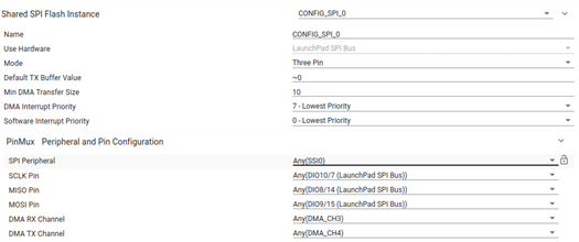
    Also Please check this below image also


  • 1. External Region Size is utilizing all 1 MB of MX25R8035F SPI flash, which is not available internally on the CC2642R (352 kB total)
    2. Internal NVS configurations do not use a SPI config, External options can choose one of the two SPI peripherals available on the device.  Default external examples use the available LaunchPad SPI configuration to interface with the on-board external flash device.
    3. Are you using the same connections as the LAUNCHXL-CC26X2R1 design files?  What changes are applied to the default example's SysConfig file?
    4. FFS implements a Flash File System using the Non-Volatile Storage (NVS) driver as the interface.  The NVS implementation of either default example appears to be identical.

    Please make sure to reference each example's README to understand more about its intended operation.  Which SimpleLink SDK version are you referencing?  If you are able to observe issues using a LAUNCHXL-CC26X2R1 then please share what steps can be used to recreate the behavior.

    Regards,
    Ryan

  • Hi

    We have checked all the possible ways from our side. Onboard flash is MX25L6433F 1MB which is working fine for us and the spi flash which we need to use is Windond W25Q32JV 4Mb flash which shows error in mounting. 
    From our brainstorming we confirmed that there is no issues with winbond devices
    We need a confirmation from you , whether any configuration is required when we go for the externl spi flashes or How can we configure new spi flash as a file system before mounting?
    Can you please help on this
  • Just to confirm, does nvsexternal and spiffsexternal work for both the MX25R8035F and MX25L6433F, and nvsexternal works for the W25Q32JV as well?  Thus only spiffsexternal on the W25Q32JV fails? Please try adding your Winbond device ID and size to the flashInfo table within the source/ti/common/extflash/ExtFlash.c file.  On that note, do you have any W25X40CL/W25X20CL device you can test with?  And do you still notice CS pin irregularity at this point?  Please provide the SDK version you are using.

    Regards,
    Ryan

  • Hi

    Yes only with spiffs it gets fails. We also saw the file which u are saying extflash.c how we can compile that bcz we couldn't find any ways to do that.

    www.ti.com/.../SIMPLELINK-CC13X2-26X2-SDK

    We are using this SDK only

  • I was mistaken, extflash.c is not involved in non-OAD projects which includes spiffsexternal.  The SPIFFS driver should have detected that no existing file system exists in memory and returned SPIFFS_ERR_NOT_A_FS, thus causing spiffsexternal.c to format a new one with SPIFFS_format.  You could try calling SPIFFS_unmount followed by SPIFFS_format and SPIFFS_mount to see whether this causes any change to the existing behavior.

    Regards,
    Ryan

  • Yeah we are trying like that only. Bu calling unmount followed by format and Mount

  • Can you please confirm that you have tested multiple W25Q32JV devices?  Please copy all source files (i.e. all .c and .h files) from source\third_party\spiffs directly into your project workspace (where spiffsexternal.c is located) in order to bypass the pre-built spiffs library.  Then you can step debug the SPIFFS_mount function in CCS to further determine exactly why this is failing.  I would also recommend that you disable Arm Compiler Optimizations from within the CCS Project Properties.  I also found more SPIFFS information inside the SDK User's Guide.

    Regards,
    Ryan

  • Hi Ryan 

    We would also confirm that we tested with multiple W25Q32JV devices also

    we are able to find out where it is causing issue in winbond spi flash W25Q32JV

    we have attached the Code piece of where it fails (spiffs_check_res function only)

    But we dont have any idea on why its failing and that what is the neccessity of the code part

    Also why this is not failing in On-board SPI flash.

    Can you please help here

  • Hi Divya,

    I'm glad you were able to find the cause of the error, unfortunately I have no experience with the third-party SPIFFS material.  It appears that the results of spiffs_phys_rd are not as expected.  You can compare the results of this function for the W25Q32JV against the internal SPIFFS and external MX25 options.  You can debug spiffs_phys_rd from spiffs_cache.c to further determine what the issue could be.

    Regards,
    Ryan