This thread has been locked.

If you have a related question, please click the "Ask a related question" button in the top right corner. The newly created question will be automatically linked to this question.

CC2650MODA: CC2650MODA- ADC not working properly

Part Number: CC2650MODA
Other Parts Discussed in Thread: CC2650, LAUNCHXL-CC2650, BOOSTXL-CC2650MA

Hello,

I am trying to use ADC in CC2650MODA. I am using pin IOID 9 in cc2650MODA to acquire values. I am applying 1.65v across the IOID 9 pin and I am getting an ADC value of 4.

I have modified the board. h and CC2650Launchxl.c file to configure IOID 9 pins. But I couldn't able to acquire the proper value.

Modifications in CC2650Launchxl.c file,

const ADCBufCC26XX_AdcChannelLutEntry ADCBufCC26XX_adcChannelLut[] = {
    {PIN_UNASSIGNED, ADC_COMPB_IN_VDDS},
    {PIN_UNASSIGNED, ADC_COMPB_IN_DCOUPL},
    {PIN_UNASSIGNED, ADC_COMPB_IN_VSS},
    {Board_DIO07_ANALOG, ADC_COMPB_IN_AUXIO7},
    {Board_DIO08_ANALOG, ADC_COMPB_IN_AUXIO6},
    {Board_DIO09_ANALOG, ADC_COMPB_IN_AUXIO5},
    {Board_DIO10_ANALOG, ADC_COMPB_IN_AUXIO4},
    {Board_DIO11_ANALOG, ADC_COMPB_IN_AUXIO3},
    {Board_DIO12_ANALOG, ADC_COMPB_IN_AUXIO2},
    {Board_DIO13_ANALOG, ADC_COMPB_IN_AUXIO1},
    {Board_DIO14_ANALOG, ADC_COMPB_IN_AUXIO0},
};

const ADCCC26XX_HWAttrs adcCC26xxHWAttrs[CC2650_LAUNCHXL_ADCCOUNT] = {
    {
        .adcDIO = Board_DIO07_ANALOG,
        .adcCompBInput = ADC_COMPB_IN_AUXIO7,
        .refSource = ADCCC26XX_FIXED_REFERENCE,
        .samplingDuration = ADCCC26XX_SAMPLING_DURATION_2P7_US,
        .inputScalingEnabled = true,
        .triggerSource = ADCCC26XX_TRIGGER_MANUAL
    },
    {
        .adcDIO = Board_DIO08_ANALOG,
        .adcCompBInput = ADC_COMPB_IN_AUXIO6,
        .refSource = ADCCC26XX_FIXED_REFERENCE,
        .samplingDuration = ADCCC26XX_SAMPLING_DURATION_2P7_US,
        .inputScalingEnabled = true,
        .triggerSource = ADCCC26XX_TRIGGER_MANUAL
    },
    {
        .adcDIO = Board_DIO09_ANALOG,
        .adcCompBInput = ADC_COMPB_IN_AUXIO5,
        .refSource = ADCCC26XX_FIXED_REFERENCE,
        .samplingDuration = ADCCC26XX_SAMPLING_DURATION_2P7_US,
        .inputScalingEnabled = true,
        .triggerSource = ADCCC26XX_TRIGGER_MANUAL
    },
    {
        .adcDIO = Board_DIO10_ANALOG,
        .adcCompBInput = ADC_COMPB_IN_AUXIO4,
        .refSource = ADCCC26XX_FIXED_REFERENCE,
        .samplingDuration = ADCCC26XX_SAMPLING_DURATION_2P7_US,
        .inputScalingEnabled = true,
        .triggerSource = ADCCC26XX_TRIGGER_MANUAL
    },
    {
        .adcDIO = Board_DIO11_ANALOG,
        .adcCompBInput = ADC_COMPB_IN_AUXIO3,
        .refSource = ADCCC26XX_FIXED_REFERENCE,
        .samplingDuration = ADCCC26XX_SAMPLING_DURATION_2P7_US,
        .inputScalingEnabled = true,
        .triggerSource = ADCCC26XX_TRIGGER_MANUAL
    },
    {
        .adcDIO = Board_DIO12_ANALOG,
        .adcCompBInput = ADC_COMPB_IN_AUXIO2,
        .refSource = ADCCC26XX_FIXED_REFERENCE,
        .samplingDuration = ADCCC26XX_SAMPLING_DURATION_2P7_US,
        .inputScalingEnabled = true,
        .triggerSource = ADCCC26XX_TRIGGER_MANUAL
    },
    {
        .adcDIO = Board_DIO13_ANALOG,
        .adcCompBInput = ADC_COMPB_IN_AUXIO1,
        .refSource = ADCCC26XX_FIXED_REFERENCE,
        .samplingDuration = ADCCC26XX_SAMPLING_DURATION_2P7_US,
        .inputScalingEnabled = true,
        .triggerSource = ADCCC26XX_TRIGGER_MANUAL
    },
    {
        .adcDIO = Board_DIO14_ANALOG,
        .adcCompBInput = ADC_COMPB_IN_AUXIO0,
        .refSource = ADCCC26XX_FIXED_REFERENCE,
        .samplingDuration = ADCCC26XX_SAMPLING_DURATION_10P9_MS,
        .inputScalingEnabled = true,
        .triggerSource = ADCCC26XX_TRIGGER_MANUAL
    },
    {
        .adcDIO = PIN_UNASSIGNED,
        .adcCompBInput = ADC_COMPB_IN_DCOUPL,
        .refSource = ADCCC26XX_FIXED_REFERENCE,
        .samplingDuration = ADCCC26XX_SAMPLING_DURATION_2P7_US,
        .inputScalingEnabled = true,
        .triggerSource = ADCCC26XX_TRIGGER_MANUAL
    },
    {
        .adcDIO = PIN_UNASSIGNED,
        .adcCompBInput = ADC_COMPB_IN_VSS,
        .refSource = ADCCC26XX_FIXED_REFERENCE,
        .samplingDuration = ADCCC26XX_SAMPLING_DURATION_2P7_US,
        .inputScalingEnabled = true,
        .triggerSource = ADCCC26XX_TRIGGER_MANUAL
    },
    {
        .adcDIO = PIN_UNASSIGNED,
        .adcCompBInput = ADC_COMPB_IN_VDDS,
        .refSource = ADCCC26XX_FIXED_REFERENCE,
        .samplingDuration = ADCCC26XX_SAMPLING_DURATION_2P7_US,
        .inputScalingEnabled = true,
        .triggerSource = ADCCC26XX_TRIGGER_MANUAL
    }
};

Modifications in CC2650Launchxl.h file

#define Board_DIO07_ANALOG          PIN_UNASSIGNED
#define Board_DIO08_ANALOG          PIN_UNASSIGNED
#define Board_DIO09_ANALOG          IOID_9
#define Board_DIO10_ANALOG          PIN_UNASSIGNED
#define Board_DIO11_ANALOG          PIN_UNASSIGNED
#define Board_DIO12_ANALOG          PIN_UNASSIGNED
#define Board_DIO13_ANALOG          PIN_UNASSIGNED
#define Board_DIO14_ANALOG          PIN_UNASSIGNED

Modifications in Board.h file

#define     Board_ADC0              CC2650_LAUNCHXL_ADC2

What might be the issue?

  • Try to refer to application note Running Standalone Bluetooth® low energy Applications on CC2650 Module (SWRA534) for porting your project to the CC2650MODA. CC2650MODA is based on 5x5 chip which is different from LAUNCHXL-CC2650 (using 7x7 chip) so you have to revise SDC pins according to datasheet 

  • I have done the modifications as per the document you have mentioned:

    Board.h file

    /* These #defines allow us to reuse TI-RTOS across other device families */
    #define     Board_LED0              Board_RLED
    #define     Board_LED1              Board_GLED
    #define     Board_LED2              Board_LED0

    #define     Board_BUTTON0           Board_BTN1
    #define     Board_BUTTON1           Board_BTN2

    #define     Board_UART0             Board_UART
    #define     Board_AES0              Board_AES
    #define     Board_WATCHDOG0         Board_WATCHDOG

    #define     Board_ADC0              CC2650_LAUNCHXL_ADC2
    //#define     Board_ADC1              Board_DIO24_ANALOG

    #define     Board_ADCBuf0           CC2650_LAUNCHXL_ADCBuf0
    #define     Board_ADCBufChannel0    (0)
    #define     Board_ADCBufChannel1    (1)

    #define     Board_initGeneral() { \
        Power_init(); \
        if (PIN_init(BoardGpioInitTable) != PIN_SUCCESS) \
            {System_abort("Error with PIN_init\n"); \
        } \
    }

    #define     Board_initGPIO()
    #define     Board_initPWM()         PWM_init()
    #define     Board_initSPI()         SPI_init()
    #define     Board_initUART()        UART_init()
    #define     Board_initWatchdog()    Watchdog_init()
    #define     Board_initADCBuf()      ADCBuf_init()
    #define     Board_initADC()         ADC_init()
    #define     GPIO_toggle(n)
    #define     GPIO_write(n,m)
    //#define     GPIO_read()

    CC2650LaunchXL.c file

    const PIN_Config BoardGpioInitTable[] = {

    //    Board_RLED   | PIN_GPIO_OUTPUT_EN | PIN_GPIO_LOW | PIN_PUSHPULL | PIN_DRVSTR_MAX,         /* LED initially off             */
    //    Board_GLED   | PIN_GPIO_OUTPUT_EN | PIN_GPIO_LOW | PIN_PUSHPULL | PIN_DRVSTR_MAX,         /* LED initially off             */
        Board_BTN1   | PIN_INPUT_EN | PIN_PULLDOWN | PIN_IRQ_BOTHEDGES | PIN_HYSTERESIS,            /* Button is active high         */
        Board_BTN2   | PIN_INPUT_EN | PIN_PULLDOWN | PIN_IRQ_BOTHEDGES | PIN_HYSTERESIS,            /* Button is active high         */
        POT_CS | PIN_GPIO_OUTPUT_EN | PIN_GPIO_HIGH | PIN_PUSHPULL | PIN_DRVSTR_MIN,
        POT_RS | PIN_GPIO_OUTPUT_EN | PIN_GPIO_HIGH | PIN_PUSHPULL | PIN_DRVSTR_MIN,
        POT_SHDN | PIN_GPIO_OUTPUT_EN | PIN_GPIO_HIGH | PIN_PUSHPULL | PIN_DRVSTR_MIN,
        Board_UART_RX | PIN_INPUT_EN | PIN_PULLDOWN,                                              /* UART RX via debugger back channel */
        Board_UART_TX | PIN_GPIO_OUTPUT_EN | PIN_GPIO_HIGH | PIN_PUSHPULL,                        /* UART TX via debugger back channel */
        Board_SPI0_MOSI | PIN_INPUT_EN | PIN_PULLDOWN,                                            /* SPI master out - slave in */
        Board_SPI0_MISO | PIN_INPUT_EN | PIN_PULLDOWN,                                            /* SPI master in - slave out */
        Board_SPI0_CLK | PIN_INPUT_EN | PIN_PULLDOWN,                                             /* SPI clock */

        PIN_TERMINATE
    };

    CC2650LaunchXL.h file

    /* Same RF Configuration as 7x7 EM */
    #define CC2650EM_5XD
    //#define CC2650EM_7ID

    /* Mapping of pins to board signals using general board aliases
     *      <board signal alias>        <pin mapping>
     */

    /* Discrete outputs */
    #define Board_RLED                  PIN_UNASSIGNED
    #define Board_GLED                  PIN_UNASSIGNED
    #define Board_LED_ON                1
    #define Board_LED_OFF               0

    /* Discrete inputs */
    #define Board_BTN1                  IOID_14
    #define Board_BTN2                  IOID_13

    /* UART Board */
    #define Board_UART_RX               IOID_1          /* RXD  */
    #define Board_UART_TX               IOID_0          /* TXD  */
    #define Board_UART_CTS              PIN_UNASSIGNED         /* CTS  */
    #define Board_UART_RTS              PIN_UNASSIGNED         /* RTS */

    /* SPI Board */
    #define Board_SPI0_MISO             IOID_10          /* RF1.20 */
    #define Board_SPI0_MOSI             IOID_11          /* RF1.18 */
    #define Board_SPI0_CLK              IOID_12         /* RF1.16 */
    #define Board_SPI0_CSN              PIN_UNASSIGNED
    #define Board_SPI1_MISO             PIN_UNASSIGNED
    #define Board_SPI1_MOSI             PIN_UNASSIGNED
    #define Board_SPI1_CLK              PIN_UNASSIGNED
    #define Board_SPI1_CSN              PIN_UNASSIGNED
    #define POT_CS                      IOID_2
    #define POT_SHDN                    IOID_8
    #define POT_RS                      IOID_7
    //#define Touch_IN                    IOID_5
    /* I2C */
    #define Board_I2C0_SCL0             IOID_3
    #define Board_I2C0_SDA0             IOID_4
    /* SPI */
    #define Board_FLASH_CS_ON           0
    #define Board_FLASH_CS_OFF          1

    /* Booster pack generic */
    #define Board_DIO0                  PIN_UNASSIGNED
    #define Board_DIO1_RFSW             PIN_UNASSIGNED
    #define Board_DIO12                 PIN_UNASSIGNED
    #define Board_DIO15                 PIN_UNASSIGNED
    #define Board_DIO16_TDO             PIN_UNASSIGNED
    #define Board_DIO17_TDI             PIN_UNASSIGNED
    #define Board_DIO21                 PIN_UNASSIGNED
    #define Board_DIO22                 PIN_UNASSIGNED

    #define Board_DIO07_ANALOG          PIN_UNASSIGNED
    #define Board_DIO08_ANALOG          PIN_UNASSIGNED
    #define Board_DIO09_ANALOG          IOID_9
    #define Board_DIO10_ANALOG          PIN_UNASSIGNED
    #define Board_DIO11_ANALOG          PIN_UNASSIGNED
    #define Board_DIO12_ANALOG          PIN_UNASSIGNED
    #define Board_DIO13_ANALOG          PIN_UNASSIGNED
    #define Board_DIO14_ANALOG          PIN_UNASSIGNED

    /* Booster pack LCD (430BOOST - Sharp96 Rev 1.1) */
    #define Board_LCD_CS                PIN_UNASSIGNED // SPI chip select
    #define Board_LCD_EXTCOMIN          PIN_UNASSIGNED // External COM inversion
    #define Board_LCD_ENABLE            PIN_UNASSIGNED // LCD enable
    #define Board_LCD_POWER             PIN_UNASSIGNED // LCD power control
    #define Board_LCD_CS_ON             1
    #define Board_LCD_CS_OFF            0

    /* PWM outputs */
    #define Board_PWMPIN0                       Board_RLED
    #define Board_PWMPIN1                       Board_GLED
    #define Board_PWMPIN2                       PIN_UNASSIGNED
    #define Board_PWMPIN3                       PIN_UNASSIGNED
    #define Board_PWMPIN4                       PIN_UNASSIGNED
    #define Board_PWMPIN5                       PIN_UNASSIGNED
    #define Board_PWMPIN6                       PIN_UNASSIGNED
    #define Board_PWMPIN7                       PIN_UNASSIGNED

    /** ==================================================================

    Am I missing anything?

  • Hi,

    This looks good to me.

    Can you share snippets of your code initializing/using ADC?

    Thanks,
    Toby

  • In main.c file

      Board_initADC();

    And I created a function to read voltage from the ADC pin. This function will be called from a task at a regular interval.

    ADC reading function:

    float read_batt_volt(){

        ADC_Handle   adc;
        ADC_Params   params;
        int_fast16_t res;


        ADC_Params_init(&params);
        adc = ADC_open(Board_ADC0, &params);
        if (adc == NULL) {
    //      System_abort("Error initializing ADC channel 0\n");
    //            while(1);
        }
        res = ADC_convert(adc, &adcValue0);
        if (res == ADC_STATUS_SUCCESS) {
        adc1=adcValue0/952.55813953488;  //To convert acquired 12 bit raw value into voltage (2^12/4.3V=952.55813953488)
        batt_volt= adc1/0.5; //To convert the voltage from voltage divider circuit into battery voltage (R18/(R18+R19)=0.5)
        }
        ADC_close(adc);
        return(batt_volt);
    }

  • For your reference, I use attached CC2650_LAUNCHXL.c/CC2650_LAUNCHXL.h/Board.h/adcsinglechannel.c and I can get ADC reading from IOID_7 on my CC2650MODA bootpack using adcsinglechannel example.

    6813.adcsinglechannel_CC2650MODA.zip

  • Hello,

    Actually, the ADC is working fine with pin 7 and pin 8. I am only facing the issue in PIN 9. Can it be an issue with the CC2650MODA?

  • I am not sure why pin9 cannot work.  can you help to verify this?

  • Hello Jamalkhan,

    Can you provide your modified CC2650_LAUNCHXL.c/CC2650_LAUNCHXL.h/Board.h/adcsinglechannel.c files so that I can better understand which parts of YK's code you've used and what remains your own?  Have you tried testing IOID10 through IOID14 as well, and what are the results of these?  Have you tried referencing similar E2E threads?

    Hi YK,

    Are you observing the same behavior as Jamalkhan and why does the CC2650_LAUNCHXL.c code you provided switch the Dio and internal signal pairs of DIO9 and DIO7?

    const ADCBufCC26XX_AdcChannelLutEntry ADCBufCC26XX_adcChannelLut[] = {
        {PIN_UNASSIGNED, ADC_COMPB_IN_VDDS},
        {PIN_UNASSIGNED, ADC_COMPB_IN_DCOUPL},
        {PIN_UNASSIGNED, ADC_COMPB_IN_VSS},
        {Board_DIO9_ANALOG, ADC_COMPB_IN_AUXIO7},   //EXPECTED DIO7
        {Board_DIO8_ANALOG, ADC_COMPB_IN_AUXIO6},
        {Board_DIO7_ANALOG, ADC_COMPB_IN_AUXIO5},   //EXPECTED DIO9
        {Board_DIO10_ANALOG, ADC_COMPB_IN_AUXIO4},
        {Board_DIO11_ANALOG, ADC_COMPB_IN_AUXIO3},
        {Board_DIO12_ANALOG, ADC_COMPB_IN_AUXIO2},
        {Board_DIO13_ANALOG, ADC_COMPB_IN_AUXIO1},
        {Board_DIO14_ANALOG, ADC_COMPB_IN_AUXIO0},
    };

    Regards,
    Ryan

  •  Yes, I see the same issue on using DIO9 to do ADC reading. I attach me code for your reference. You can check I use correct order on DIO7 and DIO9 in ADCBufCC26XX_adcChannelLut in my new attachment. I set Board_ADC0 as CC2650_LAUNCHXL_ADC2 in Board.h to use DIO9 and use Board_ADC0 in taskFxn1/Board_ADC1 in taskFxn0. When I connect DIO9 to GND, I cannot get ADC reading close to 0 and when I connect DIO9 to 3V3, I cannot get ADC reading close to 3V3. By the way, I also test this with and without R20 removed on my BOOSTXL-CC2650MA but it makes no difference.

    adcsinglechannel_ BOOSTXL-CC2650MA.zip

  • Hi YK,

    Thank you for adding so much detail to both the hardware and software.  One further recommendation at the moment is that CC2650EM_5XD replace CC2650EM_7ID in CC2650_LAUNCHXL.h.  Are you able to take accurate ADC measurements on IOID_10 through IOID_14?  Here is another E2E thread where a user was able to successfully measure CC2650MODA ADC pins.  If these recommendations are not successful then I will attempt to loop in a TI expert who has a BOOSTXL-CC2650MODA available to test with.

    Regards,
    Ryan

  • I try IOID_14 and IOID_13 and both don’t work.

  • Hi YK,

    Thanks for confirming.

    We will try to replicate this issue, and will need to wait to get some available HW (about 1 week).

    Thanks,
    Toby

  • Hi,

    Our team has reproduced this issue (DIO9 seems to not work with ADC) on BOOSTXL-CC2650MA, and are investigating potential causes.

    Can you try configuring DIO9 as output GPIO? I wonder if it could be an issue with the board itself.

    Thanks,
    Toby

  • No, I try to use DIO9 as GPO and it doesn't work at all. PIN_getOutputValue from DIO9 always return 0 eve I set it to high by using PIN_setOutputValue.

  • Hi YK,

    Thanks for confirming.

    I have reached out to HW team to check if they've seen this issue before.

    As sanity check, I verified that all analog pins on CC2650 7x7 work as expected (measuring GND and 3v3).

    Thanks,
    Toby

  • For CC2650 7x7, I had tested all ADC pins and am pretty sure they all work. Just have no idea why BOOSTXL-CC2650MA ADC only works on DIO7 and 8. Hope you can figure out this soon.

  • For my BOOSTXL-CC2650MA, I am able to read ADC values (measured 3v3, GND) on these DIOs: 7, 8, 11, 12, 13.
    ADC seems to not work on DIOs 9, 10, 14.

    However, on your side, it seems that ADC is not working on DIOs 13 and 14.

    It makes sense that DIO14 is not working -- looking at the schematic of BOOSTXL-CC2650MA, we can see DIO14 is routed through R24, which is DNM.

    , can you re-check if DIO 13 is working as ADC?
    If this is not working AND we are both using same HW (BOOSTXL-CC2650MA), then this could be due to some factor at the board level.

    , do you have a custom board which this is working on? Or are you also using BOOSTXL-CC2650MA board?

  • I try to use DIO9 as GPO and it doesn't work at all. PIN_getOutputValue from DIO9 always return 0 eve I set it to high by using PIN_setOutputValue.

    I modified a pinInterrupt example with DIO_9 as input (falling edge) -- when I connect DIO_9 to GND, I see the interrupt triggering.

    So it does look like DIO_9 has a working connection to the board header on the BOOSTXL.

  • 1. I will test DIO13 as ADC again but do you figure out why DIO9 cannot act as ASC correctly?

    2. I test DIO9 as GPO and I cannot control it to high. DIO9 is always low in my GPO test. I can test DIO9 as GPI too to see if it works. However, can you also test if GPO function works on DIO9 of your BOOSTXL?

  • 1.I test DIO13 again and I can confirm it works.

    2. I test DIO9 as GPI and it doesn't work on my board. I also test DIO7 as GPI and I am sure it works.

  • Hello Toby,

    I have tested this in a custom board and DIO9 didn't worked.

  • 1. I will test DIO13 as ADC again but do you figure out why DIO9 cannot act as ASC correctly?

    I am still looking into this. So far I don't see why it shouldn't work, since DIO9 is working as normal GPIO.
    I am going to run a few more tests today and get back to you.

    I test DIO9 as GPO and I cannot control it to high. DIO9 is always low in my GPO test. I can test DIO9 as GPI too to see if it works. However, can you also test if GPO function works on DIO9 of your BOOSTXL?


    , thanks for confirming on your end.
    I am able to configure DIO9 as output, and can see with logic analyzer that I can toggle it high and low.
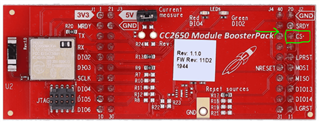
    Can you confirm that you are measuring DIO9 on the pin labeled "CS" on silk?

    (Just want to make sure, since I noticed that DIO9 has an alternate path (if R21 is populated) to a different board header).

  • I have tested this in a custom board and DIO9 didn't worked.

    thanks for confirmation.

    Can you check if DIO9 is working as normal GPIO on your custom board?

    Also, have you got this custom board reviewed by TI? If not, it could be a good option: https://www.ti.com/tool/SIMPLELINK-2-4GHZ-DESIGN-REVIEWS

  • Hi all,

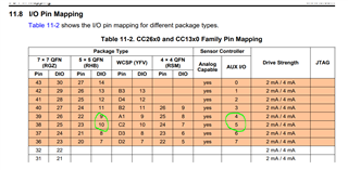
    I believe the issue is the mapping between AUXIO# and DIO# for DIO 9 and DIO 10.

    After making the below changes, I am able to read ADC values from both DIO 9 and DIO 10:

    const ADCBufCC26XX_AdcChannelLutEntry ADCBufCC26XX_adcChannelLut[] = {
    
    // ...
    
    
        {Board_DIO9_ANALOG, ADC_COMPB_IN_AUXIO4},
        {Board_DIO10_ANALOG, ADC_COMPB_IN_AUXIO5},
    
    // ...
    
    }

    const ADCCC26XX_HWAttrs adcCC26xxHWAttrs[CC2650_LAUNCHXL_ADCCOUNT] =
    {
    
    // ...
    
        { // working!! (DIO9 -- AUXIO4)
            .adcDIO = Board_DIO9_ANALOG,
            .adcCompBInput = ADC_COMPB_IN_AUXIO4,
            .refSource = ADCCC26XX_FIXED_REFERENCE,
            .samplingDuration = ADCCC26XX_SAMPLING_DURATION_2P7_US,
            .inputScalingEnabled = true,
            .triggerSource = ADCCC26XX_TRIGGER_MANUAL
        },
        { // working!! (DIO10 -- AUXIO5)
            .adcDIO = Board_DIO10_ANALOG,
            .adcCompBInput = ADC_COMPB_IN_AUXIO5,
            .refSource = ADCCC26XX_FIXED_REFERENCE,
            .samplingDuration = ADCCC26XX_SAMPLING_DURATION_2P7_US,
            .inputScalingEnabled = true,
            .triggerSource = ADCCC26XX_TRIGGER_MANUAL
        },
    
    // ...

    Please try these changes and let me know if they are working for you.

    Thanks,
    Toby

  • 1. For DIO9 as GPIO, the root cause of not working is that I remove R20. I make it work after I solder R20 back.

    2. After use AUXIO4 for DIO9 and AUXIO5 for DIO10, both ADC reading from DIO9 and 10 are correct now. Can you elaborate why we have to switch AUXIO for DIO 9 and 10?

  • This is actually documented in the TRM:

    The required AUXIO# and DIO# mappings for each package are shown here.

    The ADC example was based on 7x7 package, which has different AUXIO# to DIO# mapping -- CC2650MODA is based on 5x5 package, so please refer to the 5x5 mappings.

  • This is weird that those two AUXIOs are not in sequential order as others when you design hardware. Anyway, it’s good to figure out all of these.