This thread has been locked.

If you have a related question, please click the "Ask a related question" button in the top right corner. The newly created question will be automatically linked to this question.

CC2650: in adcbufcontinuous, the time to call the callback function is wrong?

Part Number: CC2650
Other Parts Discussed in Thread: SYSBIOS

TI engineer,

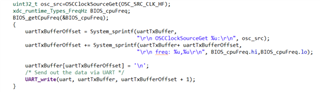
I tried the example “adcbufcontinuous_CC2650_LAUNCHXL_TI”, I set the “adcBufParams.samplingFrequency = 1000;” and “#define ADCBUFFERSIZE    (25)”. And I add some code in ADC callback function to print the time stamp, as the picture.

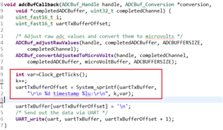
The callback function should be executed every 25ms, however the timestamp it prints show it executes every 24.85ms.

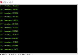
I was really confused why the time is less than 25ms,since 25*0.001=0.025s. 

  • Can you try altering your buffer size and frequency and provide the results?  What is the return value of BIOS_getCpuFreq? The main clock sources the ADC and GPTimer which determines the sampling frequency.

    Regards,
    Ryan

  • Hi, Ryan,

    I did as you said in https://e2e.ti.com/support/wireless-connectivity/bluetooth-group/bluetooth/f/bluetooth-forum/1065350/launchxl-cc2650-how-to-configure-the-clock-source-of-clock-module/3941418#3941418

    I kept adcBufParams.samplingFrequency = 1000; and #define ADCBUFFERSIZE    (25). I added Power_setDependency(PowerCC26XX_XOSC_HF); in main() and checked if it succeed by OSCClockSourceGet(OSC_SRC_CLK_HF) in conversionStartFxn, also in conversionStartFxn, I get the value of BIOS_getCpuFreq. But I didn't reconfigure the clock for a new CPU frequency or change the timer/tick source.

    now, I get these results:

    "
    OSCClockSourceGet 1:

    freq: 0,48000000


    1 timestamp 2194:


    2 timestamp 4693:

    ...

    40 timestamp 99705:


    41 timestamp 102204:

    ...

    80 timestamp 199716:


    81 timestamp 202218:

    "

    "OSCClockSourceGet 1:" shows that I successfully set the clock source to XOSC_HF, and the CPU frequency is 48MHz. And I have a problem that when it need to change the CPU frequency? since XOSC_HF is doubled internally to create a 48-MHz clock, maybe I don't need to change CPU frequency?

    As for the timestamp, it takes 24.99ms~25.02ms for every packet, which is more accurate. However, 102204-2194=100010=1000.1ms and 202218-102204=100,014=1000.14ms. and I checked many times, the time for every 40 packet is 1000.1ms~1000.14ms, which should be 1000ms. Do you have any idea why it would happen? Is it a normal situation?

    thank you

  • please allow me post my code here.


    * ======== adcBufContinuousSampling.c ========
    */

    #include <stdint.h>
    #include <stdio.h>
    /* XDCtools Header files */
    #include <xdc/std.h>
    #include <xdc/runtime/System.h>
    #include <ti/sysbios/knl/Clock.h>
    /* BIOS Header files */
    #include <ti/sysbios/BIOS.h>
    #include <ti/sysbios/knl/Task.h>

    /* TI-RTOS Header files */
    #include <ti/drivers/ADCBuf.h>
    #include <ti/drivers/UART.h>
    #include "driverlib/osc.h"
    #include <ti/drivers/Power.h>
    #include <ti/drivers/power/PowerCC26XX.h>

    #if defined(CC2650DK_7ID) || defined(CC1310DK_7XD)
    #include <ti/drivers/PIN.h>
    #endif

    /* Example/Board Header files */
    #include "Board.h"

    #define TASKSTACKSIZE (768)
    #define ADCBUFFERSIZE (25)

    Task_Struct task0Struct;
    Char task0Stack[TASKSTACKSIZE];

    uint16_t sampleBufferOne[ADCBUFFERSIZE];
    uint16_t sampleBufferTwo[ADCBUFFERSIZE];
    uint32_t microVoltBuffer[ADCBUFFERSIZE];
    uint32_t buffersCompletedCounter = 0;
    char uartTxBuffer[(10 * ADCBUFFERSIZE) + 25];

    /* Driver handle shared between the task and the callback function */
    UART_Handle uart;
    int k;
    uint_fast16_t i;
    uint_fast16_t uartTxBufferOffset;
    /*
    * This function is called whenever a buffer is full.
    * The content of the buffer is then converted into human-readable format and
    * sent to the PC via UART.
    *
    */
    void adcBufCallback(ADCBuf_Handle handle, ADCBuf_Conversion *conversion,
    void *completedADCBuffer, uint32_t completedChannel) {

    /* Adjust raw adc values and convert them to microvolts */
    ADCBuf_adjustRawValues(handle, completedADCBuffer, ADCBUFFERSIZE,
    completedChannel);
    ADCBuf_convertAdjustedToMicroVolts(handle, completedChannel,
    completedADCBuffer, microVoltBuffer, ADCBUFFERSIZE);

    int var=Clock_getTicks();
    k++;
    {
    uartTxBufferOffset = System_sprintf(uartTxBuffer,
    "\r\n %d timestamp %lu:\r\n", k,var);

    uartTxBuffer[uartTxBufferOffset] = '\n';
    /* Send out the data via UART */
    UART_write(uart, uartTxBuffer, uartTxBufferOffset + 1);
    }

    }

    /*
    * Callback function to use the UART in callback mode. It does nothing.
    */
    void uartCallback(UART_Handle handle, void *buf, size_t count) {
    return;
    }

    /*
    * ======== conversionStartFxn ========
    * Task for this function is created statically. See the project's .cfg file.
    */
    void conversionStartFxn(UArg arg0, UArg arg1) {
    UART_Params uartParams;
    ADCBuf_Handle adcBuf;
    ADCBuf_Params adcBufParams;
    ADCBuf_Conversion continuousConversion;

    /*
    * The CC2650DK_7ID and CC1310DK_7XD measure an ambient light sensor in this example.
    * It is not powered by default to avoid high current consumption in other examples.
    * The code below turns on the power to the sensor.
    */
    #if defined(CC2650DK_7ID) || defined(CC1310DK_7XD)
    PIN_State pinState;

    PIN_Config AlsPinTable[] =
    {
    Board_ALS_PWR | PIN_GPIO_OUTPUT_EN | PIN_GPIO_HIGH | PIN_PUSHPULL, /* Turn on ALS power */
    PIN_TERMINATE /* Terminate list */
    };

    /* Turn on the power to the ambient light sensor */
    PIN_open(&pinState, AlsPinTable);
    #endif

    /* Create a UART with data processing off. */
    UART_Params_init(&uartParams);
    uartParams.writeDataMode = UART_DATA_BINARY;
    uartParams.writeMode = UART_MODE_CALLBACK;
    uartParams.writeCallback = uartCallback;
    uartParams.baudRate = 115200;
    uart = UART_open(Board_UART0, &uartParams);

    uint32_t osc_src=OSCClockSourceGet(OSC_SRC_CLK_HF);
    xdc_runtime_Types_FreqHz BIOS_cpuFreq;
    BIOS_getCpuFreq(&BIOS_cpuFreq);
    {
    uartTxBufferOffset = System_sprintf(uartTxBuffer,
    "\r\n OSCClockSourceGet %u:\r\n", osc_src);
    uartTxBufferOffset += System_sprintf(uartTxBuffer+ uartTxBufferOffset,
    "\r\n freq: %u,%u\r\n", BIOS_cpuFreq.hi,BIOS_cpuFreq.lo);

    uartTxBuffer[uartTxBufferOffset] = '\n';
    /* Send out the data via UART */
    UART_write(uart, uartTxBuffer, uartTxBufferOffset + 1);
    }

    /* Set up an ADCBuf peripheral in ADCBuf_RECURRENCE_MODE_CONTINUOUS */
    ADCBuf_Params_init(&adcBufParams);
    adcBufParams.callbackFxn = adcBufCallback;
    adcBufParams.recurrenceMode = ADCBuf_RECURRENCE_MODE_CONTINUOUS;
    adcBufParams.returnMode = ADCBuf_RETURN_MODE_CALLBACK;
    adcBufParams.samplingFrequency = 1000;
    adcBuf = ADCBuf_open(Board_ADCBuf0, &adcBufParams);


    /* Configure the conversion struct */
    //#define Board_ADCBufChannel0 (3) for DIO23 as ADC input pin
    continuousConversion.arg = NULL;
    continuousConversion.adcChannel = Board_ADCBufChannel0;
    continuousConversion.sampleBuffer = sampleBufferOne;
    continuousConversion.sampleBufferTwo = sampleBufferTwo;
    continuousConversion.samplesRequestedCount = ADCBUFFERSIZE;

    if (!adcBuf){
    System_abort("adcBuf did not open correctly\n");
    }

    /* Start converting. */
    if (ADCBuf_convert(adcBuf, &continuousConversion, 1) !=
    ADCBuf_STATUS_SUCCESS) {
    System_abort("Did not start conversion process correctly\n");
    }

    /*
    * Go to sleep in the foreground thread forever. The data will be collected
    * and transfered in the background thread
    */
    Task_sleep(BIOS_WAIT_FOREVER);
    }

    /*
    * ======== main ========
    */
    int main(void) {
    Task_Params taskParams;

    /* Call board init functions */
    Board_initGeneral();
    Board_initADCBuf();
    Board_initUART();
    Power_setDependency(PowerCC26XX_XOSC_HF);

    /* Construct BIOS objects */
    Task_Params_init(&taskParams);
    taskParams.stackSize = TASKSTACKSIZE;
    taskParams.stack = &task0Stack;
    Task_construct(&task0Struct, (Task_FuncPtr) conversionStartFxn,
    &taskParams, NULL);

    System_printf("Starting the ADC Continuous Sampling example\n"
    "System provider is set to SysMin. Halt the target to view any SysMin "
    "contents in ROV.\n");

    /* SysMin will only print to the console when you call flush or exit */
    System_flush();

    /* Start BIOS */
    BIOS_start();

    return (0);
    }

  • Your results now appear to be within reason given crystal accuracy and the TI driver scaling for the GP timer which clocks the ADC interrupts.  Does the timestamp continue to drift as you gather more samples?

    Regards,
    Ryan

  • I got these data:

    1000Hz sample rate to collect 1000 ADC data, the difference between theoretical and actual time: ~0.11ms

    1000Hz sample rate to collect 2000 ADC data: ~0.25ms

    10000Hz sample rate to collect 1000 ADC data: ~0.01ms

    100Hz sample rate to collect 1000 ADC data: ~1.23ms

    the difference of time seems to be correlated with the time spent to collect ADC. But the theoretical time is always bigger than actual time. Do you think it is due to the skew of crystal oscillator?

    (I have made a mistake, that is the actual time is always bigger than theoretical time. 2022.1.3)

  • Thanks for these data points.  You can compare the terminal's local timestamp (some explain a method to enable this) against the Clock module's get ticks function to determine clock accuracy.  Otherwise the deficit is caused by the logic used to initialize the GP Timer within the ADC TI Driver, for which you could try compensating by slightly modifying the sample rate value (ex. 999 Hz instead of 1000).

    Regards,
    Ryan