This thread has been locked.

If you have a related question, please click the "Ask a related question" button in the top right corner. The newly created question will be automatically linked to this question.

CC2564CSTBTBLESW: Output power control by using VS_Set_Max_Output_Power()

Part Number: CC2564CSTBTBLESW
Other Parts Discussed in Thread: CC2564C, CC2564

Hi,

We are using the latest version of Bluetopia stack for ST (Version 5.1).

We are using this below functions to change the gain.

VS_Set_Max_Output_Power( BluetoothStackID, 0);        // to set minimum gain

VS_Set_Max_Output_Power( BluetoothStackID, 12);     //to set maximum gain

The VS_Set_Max_Output_Power function accepts values from 0 to 12 and it specifies 4 dBm steps.

1. What power is being set when we call this function with 0 and 12 ?

2. Is there any table to refer the gain corresponds to the value from 0 to 12 ?

3. Will it set immediately when we call this function or do we need to restart the chip ?

Thanks

  • Hi Ananthakrishnan,

    1. VS_Set_Max_Output_Power calls HCI_VS_DRPb_Set_Power_Vector which you can read more about here. Ultimately, the power being set depends on the modulation type (GFSK, EDR2, EDR3). It constructs the amplitude control word (ACW) for any given power level in dBm as long as it is in the supported range.

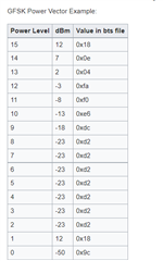
    2. We do not have an official table for the CC2564C, but I will attach the CC2564B Vendor Specific HCI Command User's Guide which includes a table for GFSK modulation. 6136.CC256x VS HCI Commands - Texas Instruments Wiki.pdf

    3. I believe this function will set power immediately.

    Thanks,
    Jacob

  • Hi,

    When I tried to change the gain to minimum and maximum I am getting the given data,

    VS_Set_Max_Output_Power( BluetoothStackID, 0);        // to set minimum gain

    Log:

    Command Name: HCI_VS_DRPb_Set_Class2_Single_Power 

    GFSK Power Level Index = 0x0f (Power Level 15)            //////// GFSK Power Level 15 Value = 0x00

    EDR2 Power Level Index = 0x0f (Power Level 15)            //////// EDR2 Power Level 15 Value = 0x00

    EDR3 Power Level Index = 0x0f (Power Level 15)            //////// EDR3 Power Level 15 Value = 0x00

    VS_Set_Max_Output_Power( BluetoothStackID, 12);        // to set maximum gain

    Log:

    Command Name: HCI_VS_DRPb_Set_Class2_Single_Power 

    GFSK Power Level Index = 0x0d (Power Level 13)          //////// GFSK  Power Level 13 Value = 0x04

    EDR2 Power Level Index = 0x0e (Power Level 14)          //////// EDR2  Power Level 14 Value = 0x0a

    EDR3 Power Level Index = 0x0e (Power Level 14)          //////// EDR3 Power Level 14 Value = 0x0a

    1. Why is it taking 0x04 in GFSK mode when I give 12? It should take 0x18 ( 2*12) right? (as per the document, it should take 0x18)

    2.We want two settings for the output power (Pout = 12dBm and Pout = -3dBm). Can you help me with the parameters that I have to set for these two Pout levels when I call the VS_Set_Max_Output_Power() function?

    I have attached the BT Logger.

  • Hi Ananthakrishnan,

    Thank you for taking logs. The WiLinkTm 8.0 Bluetooth® Vendor-Specific HCI Commands Guide is specific to the WiLink 8 I linked earlier. I apologize for the confusion with the CC2564C. You are using the correct function, VS_Set_Max_Output_Power.

    I believe you are using the command correctly. 

    1. It looks like the Power Vector table has the correct value of 0x18, but it is set at Power Level 15 instead of 13. I'm not sure why your device defaulted to Power Level 13. You can see this in your log on line #305:

    2. I'll try to help. I believe your VS_Set_Max_Output_Power( BluetoothStackID, 12);  is correct for an output power of 12 dBm. What happens if you try -3 as the second parameter?

    Do you have an RF power analyzer to double check the output power?

    Thanks,
    Jacob

  • Hi Jacob

    The VS_Set_Max_Output_Power function accepts values from 0 to 12 so we have measured the RSSI with all  parameters ( 0 to 12). There is no change in the RSSI. 

    Can you please check and let us know how to use this function to change the output power?

  • Hi Jacob,

    Could you help us by validating these settings on a silicon setup? We are not able to modify the RF power through these controls; if you need access to any of our code, we would be happy to share it with you.

    thanks!

  • Hi Sundararajan,

    I'll look into how to test this for you. How are you measuring the RSSI?

    Thanks,
    Jacob

  • Hello Jacob,

    We are using a phone app (Bluetooth RSSI analyzer) to measure the RSSI. We have done the following checks

    a) With our PCB, check the RSSI at different distances (and orientations) for the phone; this is our reference measurement

    b) We repeated the measurement at the same distances/orientation while trying to program the output power through the aforementioned settings. The RSSI did not show any change due to the settings.

    c) We put a copper strip on the antenna to reduce the radiated power, and this was correctly reflected in our RSSI measurement. We were able to reduce the RSSI by 10 to 25dB by changing the thickness of the copper strip.

    Hope this helps.

  • Hi Sundararajan,

    This is helpful. I'll try to provide useful testing information on this thread in a few days.

    Thanks,
    Jacob

  • Hello Jacob,

    Could you please try and expedite this? We are in the final stages of pre-production ramp, and this is a very critical input for us. We have mutliple radios operating simultaneously in our system, and we need to be able to control the RF output power of the CC2564C part depending on the mode we are operating in.

  • Please also keep in mind that we are using the CC2564C part.

  • Hi Sundararajan,

    I had trouble getting consistent results using the VS_Set_Max_Output_Power API. Instead, I would like to see if the procedure from the CC256x Testing Guide works for you to set TX output power continuously:

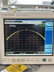
    When I added these HCI commands to the BTS in HCITester, I was able to get the max RF output power of +12 dBM.


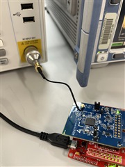
    I connected the CC2564C to a signal analyzer using a UFL connector, SMA adapter, and Co-ax cable.

    There is some loss associated with the UFL cable (~1 dBm), but I was able to see a RF output of 11.63 dBm.

    I am attaching documentation from our discontinued Wiki at this part of the thread.

    5023.CC256x VS HCI Commands - Texas Instruments Wiki.pdf

    7587.CC256x Testing Guide - Texas Instruments Wiki.pdf

    Thanks,
    Jacob

  • Hi Jacob, 

    I am Vishnu working in the team of Sundararajan & Ananth.

    I was trying to use the commands you shared with respect to the document.

    While going through the document we found these commands.

    1)  "HCI_VS_DRPb_Set_Power_Vector", by which we can update the Power vector Table.

    2)  "HCI_VS_DRPb_Set_Class2_Single_Power",  to disable the Power Control  Feature and use a Single Power.

    3)  "HCI_VS_LE_Output_Power", to set the BLE output Power.

     We are unable to find this command in the Bluetopia Stack version  v5.1 (Latest Release).  

    As we are using it on the application level (with STM32+CC2564C solution), We can't use the HCITester to do the HCI Commands.

    Can you help me to use this command?.

    Do you have any example which I can use to call this function from the stack to get this done?

    Thanks,

    Vishnu

  • Hi Jacob, 

    I am adding some HCI_logs from BT-logger when I am using the VS_Set_Max_Output_Power(BluetoothStackID,Power).

    I am calling this function just after enabling the BLE feature.

    With  VS_Set_Max_Output_Power(BluetoothStackID,0)

    With  VS_Set_Max_Output_Power(BluetoothStackID,6)

    With  VS_Set_Max_Output_Power(BluetoothStackID,12)

    Power Level values don't seem to be correct.

    The values 0xd8, 0x00, 0xe4, etc are not there in the Power vector table mentioned in the 3568.CC256x VS HCI Commands - Texas Instruments Wiki.pdf

    Is this causing the issue?

    Thanks,

    Vishnu

  • Hello Jacob,

    Did you get a chance to take a look at this?

    Please review Vishnu's inputs in detail and help us arrive at a solution at the earliest.

    thanks!

  • Hi Vishnu and Sundararajan,

    I’ll follow up here tomorrow.

    Thanks,

    Jacob

  • Thanks Jacob. Look forward to hearing from you

  • Hi Sundararajan and Vishnu,

    I understand that you cannot use HCITester to interact with your MCU since you do not have the HCI interface available. Instead, I recommend you use the HCI_Send_Raw_Command function in HCIAPI.h to send the HCI commands in the application.

    Can you try sending these commands to your device using HCI_Send_Raw_Command? 

    Send_HCI_VS_DRPb_Set_Power_Vector 0xFD82, 0x00, -50 *2, -18 *2, -18 *2, -18 *2, -18 *2, -18 *2, -18 *2, -18 *2, -18 *2, -14 *2, -10 *2, -6 *2, -2 *2, 2 *2, 6 *2, -20 *2, 0xFF, 0x00
    
    Send_HCI_VS_DRPb_Tester_Con_TX 0xFD84, 0x1, 0, 0, 15, 0x00000000, 0x00000000
    
    HCI_VS_Write_Hardware_Register 0xFF01, 0x0019180c, 0x0101
    
    HCI_VS_DRPb_Enable_RF_Calibration 0xFD80, 0xFF, 0xFFFFFFFF, 0x01

    I recommend using HCITester to edit the parameters so you can select the desired power level index for the output power. 

    Thanks,
    Jacob

  • Thanks; we will check and revert

  • Hi Jacob,

    I tried sending these commands from our Application. After this command, I am not able to find the device on my phone.

    I also tried by removing the  Send_HCI_VS_DRPb_Tester_Con_TX 0xFD84, 0x1, 0, 0, 15, 0x00000000, 0x00000000 (as we are using it in application).

    I am attaching the BT logger file here.


    The first command I send starts from line no 4652.

    Can you please check what is wrong here?

    Thanks,

  • Hi Vishnu,

    I'll take a look at these commands and follow up tomorrow.

    Thanks,
    Jacob

  • Hi Vishnu,

    I'm having a problem opening these Google Drive links at the moment. Can you attach the logs directly to this thread?

    Thanks,
    Jacob

  • HI Jacob,

    I was not able to directly attach the files. That is the reason I tried attaching google links.

     I will make it available over mail by the team.

    Thanks,

  • Hi Jacob,

    See if you can access it now, for some reason option to attach a file was not working.

    But Drag and drop seems to work.

    Vs_Set_maxOutputPower_log.zip

    Thanks,

  • Hi Vishnu,

    I don't see any errors immediately when looking at your logs. It seems like the HCI_VS_DRPb_Tester_Con_TX command is successful setting the power to level 15 (max RF output power):

    Do you notice a change in the RSSI? 

    I tried sending these commands from our Application. After this command, I am not able to find the device on my phone.

    These commands tell the CC2564C to transmit at a certain output power level and frequency. This is usually used for test purposes; perhaps these commands interrupt Bluetooth advertising operations. I'd recommend validating the output power and then addressing Bluetooth functionality.

    Thanks,
    Jacob

  • The latest logs of test we done is attached here. In this we are updating the power Vector Table with only one single value(-50dB or 0x9c). We did this to check if the power table entries are being honoured. ( lower power level would show in RSSI measurements very easily ) Also tried using the HCI_VS_DRPb_Set_Class2_Single_Power command.

    After that doing the RF Calibration. (Step mentioned to change power in the CC256x VS HCI Commands).

    We tried calling this function just after Enabling the BLE feature(in Openstack()) and also tried calling the function after doing the advertisement. Nothing seems to change the output power. The RSSI measured was equivalent to the 12dB power setting. No change was observed in the RSSI at the same distances.

    We need to do the control in Application mode. ( In the past, we have managed to changed the power levels in the Test modes, now we want to control the power from our application ).

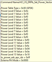
    /*******************************************************************************Log-Start*************************************************************************************/ 1433 1 12:38:47.309 +0:45:13.721 HCI/LMP viewer 1 0x00002798 0x00002798 HCI_VS_DRPb_Set_Power_Vector Command Name:HCI_VS_DRPb_Set_Power_Vector

    • Power Table Type = 0x00 (GFSK)
    • Power Level 0 Value = 0x9c
    • Power Level 1 Value = 0x9c
    • Power Level 2 Value = 0x9c
    • Power Level 3 Value = 0x9c
    • Power Level 4 Value = 0x9c
    • Power Level 5 Value = 0x9c
    • Power Level 6 Value = 0x9c
    • Power Level 7 Value = 0x9c
    • Power Level 8 Value = 0x9c
    • Power Level 9 Value = 0x9c
    • Power Level 10 Value = 0x9c
    • Power Level 11 Value = 0x9c
    • Power Level 12 Value = 0x9c
    • Power Level 13 Value = 0x9c
    • Power Level 14 Value = 0x9c
    • Power Level 15 Value = 0x9c
    • tx_power_edr_epc_idx = 0xff
    • Externa PA Mode = 0x0000

    1434 4 12:38:47.317 +0:45:13.729 HCI/LMP viewer 1 0x00002798 0x00002798 HCI_Command_Complete_VS_DRPb_Set_Power_Vector_Event Event Name: HCI_Command_Complete_VS_DRPb_Set_Power_Vector_Event

    Number HCI commands = 0x01 Command Opcode = 0xfd82 Status = 0x00 (Success) 1435 1 12:38:47.317 +0:45:13.729 HCI/LMP viewer 1 0x00002799 0x00002799 HCI_VS_DRPb_Set_Power_Vector Command Name:HCI_VS_DRPb_Set_Power_Vector

    • Power Table Type = 0x01 (EDR 2MB)
    • Power Level 0 Value = 0x9c
    • Power Level 1 Value = 0x9c
    • Power Level 2 Value = 0x9c
    • Power Level 3 Value = 0x9c
    • Power Level 4 Value = 0x9c
    • Power Level 5 Value = 0x9c
    • Power Level 6 Value = 0x9c
    • Power Level 7 Value = 0x9c
    • Power Level 8 Value = 0x9c
    • Power Level 9 Value = 0x9c
    • Power Level 10 Value = 0x9c
    • Power Level 11 Value = 0x9c
    • Power Level 12 Value = 0x9c
    • Power Level 13 Value = 0x9c
    • Power Level 14 Value = 0x9c
    • Power Level 15 Value = 0x9c
    • tx_power_edr_epc_idx = 0xff
    • Externa PA Mode = 0x0000

    1436 4 12:38:47.317 +0:45:13.729 HCI/LMP viewer 1 0x00002799 0x00002799 HCI_Command_Complete_VS_DRPb_Set_Power_Vector_Event Event Name: HCI_Command_Complete_VS_DRPb_Set_Power_Vector_Event

    Number HCI commands = 0x01 Command Opcode = 0xfd82 Status = 0x00 (Success) 1437 1 12:38:47.317 +0:45:13.729 HCI/LMP viewer 1 0x0000279A 0x0000279A HCI_VS_DRPb_Set_Power_Vector Command Name:HCI_VS_DRPb_Set_Power_Vector

    • Power Table Type = 0x02 (EDR 3MB)
    • Power Level 0 Value = 0x9c
    • Power Level 1 Value = 0x9c
    • Power Level 2 Value = 0x9c
    • Power Level 3 Value = 0x9c
    • Power Level 4 Value = 0x9c
    • Power Level 5 Value = 0x9c
    • Power Level 6 Value = 0x9c
    • Power Level 7 Value = 0x9c
    • Power Level 8 Value = 0x9c
    • Power Level 9 Value = 0x9c
    • Power Level 10 Value = 0x9c
    • Power Level 11 Value = 0x9c
    • Power Level 12 Value = 0x9c
    • Power Level 13 Value = 0x9c
    • Power Level 14 Value = 0x9c
    • Power Level 15 Value = 0x9c
    • tx_power_edr_epc_idx = 0xff
    • Externa PA Mode = 0x0000

    1438 4 12:38:47.317 +0:45:13.729 HCI/LMP viewer 1 0x0000279A 0x0000279A HCI_Command_Complete_VS_DRPb_Set_Power_Vector_Event Event Name: HCI_Command_Complete_VS_DRPb_Set_Power_Vector_Event

    Number HCI commands = 0x01 Command Opcode = 0xfd82 Status = 0x00 (Success) 1439 1 12:38:47.317 +0:45:13.729 HCI/LMP viewer 1 0x0000279B 0x0000279B HCI_VS_DRPb_Set_Class2_Single_Power Command Name:HCI_VS_DRPb_Set_Class2_Single_Power

    • GFSK Power level index = 0x0d (Power Level 13)
    • EDR2 Power level index = 0x0e (Power Level 14)
    • EDR3 Power level index = 0x0e (Power Level 14)

    1440 4 12:38:47.317 +0:45:13.729 HCI/LMP viewer 1 0x0000279B 0x0000279B HCI_Command_Complete_VS_DRPb_Set_Class2_Single_Power_Event Event Name: HCI_Command_Complete_VS_DRPb_Set_Class2_Single_Power_Event

    Number HCI commands = 0x01

    • Command Opcode = 0xfd87
    • Status = 0x00 (Success)

    1441 1 12:38:47.322 +0:45:13.734 HCI/LMP viewer 1 0x0000279C 0x0000279C HCI_VS_Write_Hardware_Register Command Name:HCI_VS_Write_Hardware_Register

    • Address = 0x0019180c
    • Value = 0x0001

    1442 4 12:38:47.323 +0:45:13.735 HCI/LMP viewer 1 0x0000279C 0x0000279C HCI_Command_Complete_VS_Write_Hardware_Register_Event Event Name: HCI_Command_Complete_VS_Write_Hardware_Register_Event

    Number HCI commands = 0x01

    • Command Opcode = 0xff01
    • Status = 0x00 (Success)

    1443 1 12:38:47.323 +0:45:13.735 HCI/LMP viewer 1 0x0000279C 0x0000279C HCI_VS_DRPb_Enable_RF_Calibration Command Name:HCI_VS_DRPb_Enable_RF_Calibration

    Mode = 0xff

    Calibration Procedures Selection = 0xffffffff (Pre RF init|Clock Dependant Calc|Temperature recognition|DC|LDO|DCO Current Optimization|DCO Coarse Open Loop|KDCO Nominal Current|PPA LDO Current|TPC|IFA Pole Location|LPS|Wide Band RSSI TH|IQ MM|Don't Change) Override Temp Condition = 0x01 (Override temp changes)

    1444 4 12:38:47.323 +0:45:13.735 HCI/LMP viewer 1 0x0000279D 0x0000279D HCI_Command_Complete_VS_DRPb_Enable_RF_Calibration_Event Event Name: HCI_Command_Complete_VS_DRPb_Enable_RF_Calibration_Event

    Number HCI commands = 0x01

    • Command Opcode = 0xfd80
    • Status = 0x00 (Success)

    /*******************************************************************************Log-End*************************************************************************************/

  • We are still in the dark. Can we please discuss next steps over a call Thursday or Friday morning Dallas time?

  • Hi Sundararajan,

    I'll reach out over email. 

    Thanks,
    Jacob

  • Hi Sundararajan,

    The latest logs of test we done is attached here. In this we are updating the power Vector Table with only one single value(-50dB or 0x9c). We did this to check if the power table entries are being honoured. ( lower power level would show in RSSI measurements very easily ) Also tried using the HCI_VS_DRPb_Set_Class2_Single_Power command

    Did you include a link to the logs, or were you just referring to the text posted above?

    Thanks,
    Jacob

  • Hi - was referring to the text.

  • Hi Sundararajan,

    Understood, I'll have more information tomorrow.

    Thanks,
    Jacob

  • Thanks Jacob. This is turning out to be a critical issue for our product, and we really need your help to address this quickly. I am sure you will agree that controlling the RF power in the application is a relatively basic requirement, and it is a capability that is advertised in the CC2564 IC.

  • Hi Sundararajan,

    I tried testing the VS_Set_Max_Output_Power API with a signal analyzer again, and I was able to see changes in the output power. I tried this with the STM32 Bluetopia 5.1 stack. I'll follow up with signal anaylzer captures.

    Thanks,
    Jacob

  • Thanks Jacob; look forward to receiving the captures. Can you please share the code as well?

  • Hi Sundararajan,

    I am attaching the captures and the code in this post. You will notice that each capture is a bit off from the actual value (see file name); this is likely due to some delay between the capture max peak and the actual transmitted max peak output power.

    static int SetOutputPower(ParameterList_t *TempParam)
    {
    	int Result;
    	if(BluetoothStackID)
    	{
    		if ((TempParam->Params[0].intParam <= 12))
    		{
    			Result = VS_Set_Max_Output_Power(BluetoothStackID, TempParam->Params[0].intParam);
    		}
    		else
    		{
    			Display(("Specified value is not in the correct parameters")); 
    			Result = VS_Set_Max_Output_Power(BluetoothStackID, 0);
    		}
    	}
    	else
      {
       /* No valid Bluetooth Stack ID exists.                            */
       Result = INVALID_STACK_ID_ERROR;
      }
    		return Result;
    }

    You can check if you notice a change in the output power by running "Inquiry" after the custom "SetOutputPower" API above. "SetOutputPower" just takes the specified dBm as a parameter through the command line.

    2671.SPPDemo.c

    RF_Output_Captures.zip

    Thanks,
    Jacob

  • Thanks for the data Jacob. Please give us a couple of days to come back to you.