This thread has been locked.

If you have a related question, please click the "Ask a related question" button in the top right corner. The newly created question will be automatically linked to this question.

CC2564CSTBTBLESW: CC2564CSTBTBLESW

Part Number: CC2564CSTBTBLESW
Other Parts Discussed in Thread: CC2564C

Hi Team,

We are using the CC2564C chipset with the latest 5.1 Stack. We are trying to perform and get certification for FCC and CE.

Our Application actually uses both  BLE and BT.

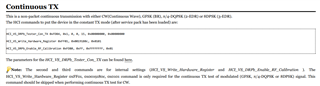
We are able to set the device in different continuous mode Transmissions and with different modulations using the FCC test mode function.

As we don't have any of the HCI pins available for access easily, we are not using the HCI Tester tools. We have written the commands in our application code itself to do the switch.

by this, we are able to switch between tests easily.

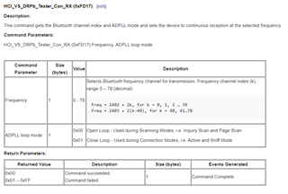
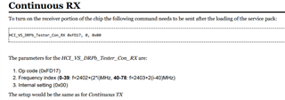
The challenge we are facing is, to set the device in Continuous RX mode. 

Is there any command I can use from the Bluetopia stack to get this done?

If you have some application code examples to do the Continuous Rx test modes with guidelines that will be great.

As the wiki Pages (where most of the related content was mentioned) are not available as TI discontinued Wiki).

Regards

  • Hi Vishnuprasad,

    I think you need the "HCI_VS_DRPb_Tester_Con_RX (0xFD17)" command:

    Unfortunately, this command was not included in the BTVS.c (VS API's). However, you can still run this command via the "HCI_Send_Raw_Command" API. You can find some examples of how this API is called in the BTVS.c file. 

    I am also attaching documents from the discontinued Processors Wiki that may be helpful.

    3568.CC256x VS HCI Commands - Texas Instruments Wiki.pdf

    8715.CC256x Testing Guide - Texas Instruments Wiki.pdf

    6170.CC256x Production Line Testing Guide - Texas Instruments Wiki.pdf

    Thanks,
    Jacob

  • Hi Jacob,

     Thanks for the materials.

    Some more Clarifications I like to get are.

    The following is the Test I have to Perform, If you can let me know what all commands to use in the sequence,  that will be great.

    1)AIM: To perform the RX mode test by putting one CC2564C Device in RX mode(Device A)  and another CC2564C device in TX mode(Device B).

    Let Device A mac address be AA:AA:AA:AA:AA:AA 

    Let Device B mac address be BB:BB:BB:BB:BB:BB

    From Device B continuously do the Transmission with some data(let's say PA9 pattern ) to Device A.

    Print out the received data from Device A.

    what all HCI commands should I use on Device A side and what all should I use on the Device B side.

    Background on our Hardware architecture

    We are using CC2564C+STM32F4 uc With Bluetopia v5.1 with freertos.

    From CC2564C to STM32F4 we have the 4 wire HCI UART communication in Place.

    From STM we have a 2 wire UART coming out, which we can use for giving commands over UART.

     On the guides, it is not clearly mentioned how to put two CC2564C  devices to perform this test.  If TI had some sample applications based on Uart commanding, other than HCI, that would have been great( somewhat like your Demo examples which are good enough and self-explaining).

    If you can get the answer for this that will be great.

    Thanks,

    Vishnu

  • Hi Vishnuprasad,

    I'll provide some guidance in a few days.

    Thanks,
    Jacob

  • Hi Jacob,

    Thanks for the Response.

    Yes, I can wait for this Week.

    If you can test the sequence at your RF lab and give me a clear picture of what to do that will be great.

    thanks,

    Vishnu

  • Hi Vishnuprasad,

    I'm not sure about the data pattern PA9, but you can put the CC2564C device in continuous RX or TX mode by adding HCI commands to the BTS. For example, in the CC256X Testing Guide:

    Continuous TX

    Continuous RX 

    Can you try using these HCI commands? You may want to check out HCITester to edit the BTS.

    Thanks,
    Jacob

  • Hi Jacob,

    We have tried this.

    But there is no clue on how we can verify that it is working.

    How can we say the device is in RX mode and the device is receiving the packets?

    Thanks,

    Vishnu

  • Hi Vishnu,

    The first step is to ensure the HCI command is successful. When you run the "HCI_VS_DRPb_Tester_Con_RX" command, you can check the output in HCITester. Do you receive a command success in the terminal?

    I'll look into how to tell if the controller is receiving packets.

    Thanks,
    Jacob

  • Hi Vishnu,

    You may also be able to use a Bluetooth sniffer to see if the packets are being sent to the Bluetooth address of the device you set in RX mode.

    Thanks,
    Jacob

  • Hi Jacob,

    Unfortunately, we don't have any sniffer to validate this.

    The HCI_VS_DRPb_Tester_Con_RX  I can check the return value from Bluetopia Stack.

    As I already mentioned with our setup, I won't be able to connect the device directly to HCITester (as the HCI pins from Chip are not exposed to connect the UART). I am not sure about validating with HCI Tester.

    With the CC2564C module are you able to run the test mentioned above?

    Is the case working with your setup?

    Regards,

  • Hi Vishnu,

    As I already mentioned with our setup, I won't be able to connect the device directly to HCITester (as the HCI pins from Chip are not exposed to connect the UART). I am not sure about validating with HCI Tester.

    How do you program the device? Do you use an IDE like Keil or IAR? It is the same process for HCITester; you do not need the HCI pins, you just need to be able to communicate with the STM32 through UART.

    I have tried the HCI_VS_DRPb_Tester_Con_TX command in HCITester and was able to set multiple output RF power levels. Here is a picture of the signal analyzer after I ran the Continuous TX commands above:

    Can you try running an HCI command in HCITester?

    Thanks,
    Jacob