This thread has been locked.

If you have a related question, please click the "Ask a related question" button in the top right corner. The newly created question will be automatically linked to this question.

CC1352P: Ripple on internal DCDC

Part Number: CC1352P
Other Parts Discussed in Thread: ENERGYTRACE

Hello E2E

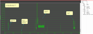
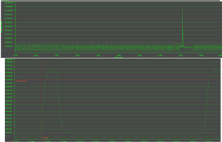
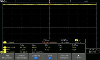
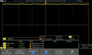
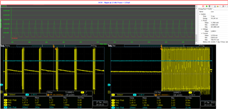
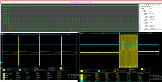
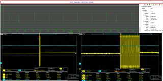
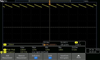
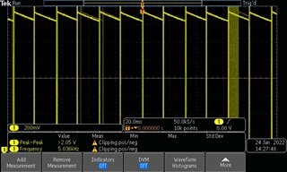
We still have struggle on ripple problem. After battery inserted to our board some of our products starting consuming excessive power (30 uA normal consumption - > 500uA DCDC after problem consumption) and starting to generate sawtooth ripple on DCDC output at Vpp ~120mV and different frequencies on different boards. Measurements from two sides of DCDC coil is like below.


We created a test setup with 40 devices. Half of theese devices powered with supply at 3v and other half 3.6v. We thought maybe this problem caused by battery but seems it not relevant on these tests. What can be root cause some of devices breaks down in time?


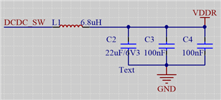
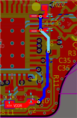
We made HW revisions but still it happens. I attaching layout of DCDC side, can you verify that the layout is OK?

Thank You! 

  • Hi, 

    When the device operates in standby mode it is expected to have a sawtooth on VDDR. To save power in standby mode, the DCDC is shut on and off periodically to re-charge VDDR. When VDDR drops below a certain threshold voltage (approx. 1.5 V), the DCDC turns on again to recharge VDDR (up to approx. 1.7 V). This is seen in both of your plots above - so your device is behaving as expected. 

    What SW are you running on your devices? Is the device operating in standby mode when you measure a current consumption of 30 uA and 500 uA? I would expect closer to 1 uA consumption in this mode of operation (BTW, how are you measuring current consumption? Please review this app note: https://www.ti.com/lit/pdf/SWRA478

    -Simon

  • Hi Simon,

    Thank You for your response, i want to give more detail

    Our firmware based on Simple peripheral OAD and our consumption elements is like below and its on standby %99.8 of period

    But when DCDC peak to peak get higher than normal, extra current peaks appears and power consumption rises. Only fix is changing 1352P with new one and flashing same FW.

    Actually DCDC out is flat in beginning, ripple is too low like below: (Two side of coil)

    Some of boards generating less ripple and don't consumpt extra power like below (Two side of coil)

    (Oscilloscope scale/div's same as first post, with that Vpp consumptions rises)

    We measuring curret by energytrace with follow SWRA478D and we have a bench multimeter gives same results.

    Our custom board power consumption is when on standby mode with empty RTOS project: ~1,5 uA. on deepsleep: ~0,5uA.

    Strange thing is this not happen all boards at close time. Some of them never breaks down. Something at BLE connection can be cause of this permenant damage ?

    Again, Thank You for your help!

  • Hey, 

    I just want to make sure you are not measuring directly on the xtal when testing these boards? This might stop the oscillator and then the DCDC will stop in a bad state which can break the device. 

    -Simon

  • Hey Simon,

    We don't make any measurements on xtal and trying to not touch it. Beside our test setups, some of returned product have same problem too.

  • Hi, 

    Ripple is expected when operating in standby mode, and the Vpp level and frequency of the ripple will vary with temperature, VDDS etc. 

    If you run your SW on a LaunchPad, is the current consumption as expected then? We need to understand if the root cause is HW or SW. 

    -Simon

  • For the first post in this thread, the right image with the higher ripple: I looks like the VDDR voltage goes down before VDDR starts going down again. Could you zoom in on this to show how low VDDR goes?

    Zoom in on this part:

    Could you run the "empty" example on the board and see if that makes a difference? This is a much simpler example and easier to see what is going on.

  • Hello evreyone, thank a lot for responses,

    I run empty example with our pin config and in healty board consumes 1,5 uA. With the boards hawe issue voltage and current mesaurements as same as our firmware. I had run our FW in devkit too it didn't consume extra power in short term. I will make long term test too.

    Here is 3 different broke down board from test setup. Power supply @3,6V 1A.  All started ripple at different frequencies and current ripples at same frequency.

    FW code is

    int main(void)
    {

    Board_init();
    flash_init();
    flash_open();
    flash_close();

    BIOS_start();

    return (0);
    }

  • What is the exact part number for L1? I want to see if it's some basic errors in the HW. 

  • In 2 HW revision we have same problem, old HW L1 is MLZ2012N6R8LT000 and the new HW L1 is MLZ1608N6R8LTD25

  • Hello;

    Could you notice some errors?

    Thank You.

  • Hi, 

    We have received your design files and will provide you feedback to the design offline. 

    -Simon

  • Hi Simon,

    Allright, we will wait for your feedback

    Thank you for your attention.

  • Feedback is provided over email. Closing this thread. 

    -Simon