This thread has been locked.

If you have a related question, please click the "Ask a related question" button in the top right corner. The newly created question will be automatically linked to this question.

CC2640: UART read callback function suddenly stops being triggered

Part Number: CC2640

My ProjectZero based project which has been working with a UART read callback function has suddenly stopped having the UART read callback being triggered from one debug session to the next without me knowingly changing any code or project settings .

This is a large project (over 6000 lines of my own code added) and I am close to running out of both Flash and SRAM, however as reported by ROV, my stack sizes are fine (even too big for hwiStackSize) and my Heap usage is well below max size with no errors.

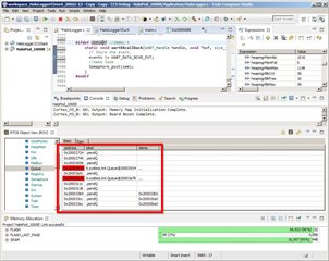
ROV does report some sort of Queue error as shown in the below images, do these Queue errors mean anything with regard to my current issue?

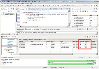
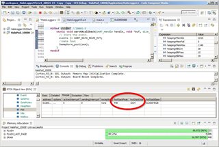
Are there any other ways of trying to find out why the UART read callback is not triggering anymore?

Thanks,

Dale

EDIT: I failed to mention that other than the UART read callback not being triggered I can not find any other operational issues when the code is running. (even UART writes work).

  • Here is the full UART code:

        #ifdef USEUART //20001-5
            void UARTcloseopen(void) //nex-1 //can not be called from the main loop!!!!
            {
              uartParams.readMode     = UART_MODE_CALLBACK; //nex-2
              uartParams.readCallback = uartRXcallback;     //nex-2
              uartParams.writeMode= UART_MODE_BLOCKING;
              uartParams.readEcho = UART_ECHO_OFF;
              uartParams.readDataMode = UART_DATA_BINARY;
              uartParams.writeDataMode = UART_DATA_BINARY;
              uartParams.baudRate = 115200;
              uartParams.dataLength = UART_LEN_8;
              uartParams.parityType = UART_PAR_NONE;
              uartParams.stopBits = UART_STOP_ONE;
              if (uartHandle != NULL)  {
                  UART_close(uartHandle);
              }
              uartHandle = UART_open(Board_UART0, &uartParams);
              if (uartHandle == NULL)
              {
                  //while (1); // get rid of this hang point - just took it out for now :)
              } else {
                  UART_read(uartHandle, &rxByte, 1); //testuart 1 byte //this read is necessary
                                                     //to turn Rx ON for continuous reads
              }
            }
        #endif
        #ifdef USEUART //20001-5
            static void uartRXcallback(UART_Handle handle, void *buf, size_t count) { //nex-2
              UART_read(uartHandle, &rxByte, 1); //testuart 1 byte //this read is necessary
                                                 //to turn Rx ON for continuous reads
              // Store the event.
              events |= UART_DATA_RCVD_EVT;
              //Wake task
              Semaphore_post(sem);
            }
        #endif

    I found hundreds of parameters related to UART status in the expression "uartCC26XXObjects" here are some, notably showing that the UART status is UART_OK in this debug session that has executed line 5967 to begin continuous reads yet the debug session is running and never breaks at the breakpoint on line 5974:

    If someone who understands all these hundreds of  parameters in the expression "uartCC26XXObjects" can tell me what tree to expand to further debug this issue it would be appreciated Slight smile

    EDIT: And here is the start of the data that arrives at the UART RX pin after the above debug session has started (when I expect the callback to trigger as it has in the past):

  • On a lark, I decided to try another of our identical custom pcbs which we have the CC2640F128 on.

    I guess somehow, the digital I/O pin on the 1st board suddenly stopped working since the 2nd board works fine with the above code.

    Topic issue resolved :) (I think)

    Now why would a digital I/O pin just stop working??

  • Hi Dale,

    I'm glad you resolved the original issue. If you are curious about why the DIO seemed to just stop working, I would recommend isolating the issue by writing a small section of code that uses just the UART, or even just that particular DIO as an input to see if it's truly a hardware problem. Can you detect when that pin goes high/low after you've removed all the other code on the CC2640?

    Best,

    Nate

  • Hi Nate,

    I have to write this up anyway so I might as well tell the world ;)

    For debugging purposes I decided to put the UART RX on DIO_13, which was not used on the pcb but it was not terminated at a proper solder hole for a 0.025" square header pin since there were no plans to use it.  In release mode, the Rx pin will be a properly traced JTAG_TCKC which I obviously can not debug on.

    Anyway, when I soldered the header pin into the DIO_13 pcb hole, the solder did not wick fully to the top of the pcb.  After a number of ham fisted female header installs in a very tight case, the male header pin solder pad on the bottom of the pcb separated from the pcb and instantly broke the small 0.015" trace to the CC2640.

    I have taken the yellow stop off the header pin and exposed the top solder pad under it.  Then I flowed solder up the pin on the top of the pcb, problem solved for now :)  (can't take a pic since already back in the case).

    Here are top and bottom pics of the header before the fix of the 2nd pcb...

    Thanks for following my self inflicted pain Slight smile

    Dale