This thread has been locked.

If you have a related question, please click the "Ask a related question" button in the top right corner. The newly created question will be automatically linked to this question.

LAUNCHXL-CC26X2R1: A 0x00 is pre-appended to SPI Slave transmit packet when SPI Master clocks 1 more byte than Slave's max bytes

Part Number: LAUNCHXL-CC26X2R1
Other Parts Discussed in Thread: SIMPLELINK-CC13XX-CC26XX-SDK, SYSCONFIG

Hello,

I'm experiencing an issue very similar to the following link but there was no response in this link: https://e2e.ti.com/support/wireless-connectivity/sub-1-ghz-group/sub-1-ghz/f/sub-1-ghz-forum/989368/cc1312r-cc1312-to-cc1310-spi-transfer-issue/3662432?tisearch=e2e-sitesearch&keymatch=SPI%2525252520transfer%2525252520preappends%2525252520byte#3662432

I have the SPI slave setup as:

spiParams.transferMode = SPI_MODE_CALLBACK;
spiParams.transferTimeout = (uint32_t)SPI_WAIT_FOREVER;
spiParams.transferCallbackFxn = (SPI_CallbackFxn)FSL_SPICallback;
spiParams.mode = SPI_SLAVE;
spiParams.bitRate = 4000000;
spiParams.dataSize = 8;
spiParams.frameFormat = SPI_POL0_PHA1;
spiParams.custom = NULL;

I have the tx and rx buffers sized at 262 bytes.

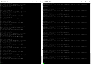
When I call SPI_Transfer, the tx buffer is set as 0xB1 0x00 0x01 0x27 0xE0 0x00 0x40 0xBF with the rest filled with 0x00

However, on the master side, I receive 0x00 0xB1 0x00 0x01 0x27 0xE0 0x00 0x40 0xBF

The master is clocking 263 bytes when this happens.  If I set the master to clock 262 bytes, then the master receives the correct data with no pre-appended 0x00 (0xB1 0x00 0x01 0x27 0xE0 0x00 0x40 0xBF 0x00 0x00).  The master is configured for the same bit rate and frame format.

Shouldn't the slave spi driver be able to handle any amount of clock cycles from the master?

Thanks,

Dawn

  • Hello Dawn,

    Which SIMPLELINK-CC13XX-CC26XX-SDK version are you referencing?  Also, what happens if you reduce the bitRate or increase the master clock cycles?  As stated in the SPI.h TI Driver Runtime APIsThe SPI slave must call SPI_transfer() before the SPI master starts transmitting. Some example application mechanisms could include:

    • Timed delays on the SPI master to guarantee the SPI slave is ready for a SPI transaction.
    • A form of GPIO flow control from the slave to the SPI master to notify the master when ready.

    Regards,
    Ryan

  • Hi Ryan,

    We are using simplelink_cc13x2_26x2_sdk_5_10_00_48.

    We are using the MRDY and SRDY flow control signals as described in NPI/UNPI.  SPI_transfer() is called in the MRDY interrupt handler and MRDY acts as the chip select.

    I've tried both 4MHz and 1MHz bit rates and they behave the same.

    I've used different master clock cycles and here's the data:

    262 bytes --> slave max tx and rx buffer size.  Transfers have no issues.

    263 bytes--> 0x00 pre-appended to the data transmitted from the slave.

    264 through 273 bytes as well as 279 bytes --> Transfers have no issue.

    In conclusion, the bitRate doesn't seem to matter but only slave buffer size + 1 master clock cycles exhibits the issue.

    Dawn

  • This is quite curious behavior.  You could try testing with the SIMPLELINK-CC13XX-CC26XX-SDK v5.40 as well but I am not aware of any resolved bugs which would address this issue.  Are you able to replicate this behavior with the spislave example as well?  This would help isolate the issue between the BLE UNPI or SPI TI Driver.  Could you make the transfer buffer larger than the SPI_Transaction count to alter behavior?

    Regards,
    Ryan

  • Hi Ryan,

    I was able to reproduce the issue with the spimaster and spislave examples.  I changed the spislave to send 0x11 0x22 0x33, etc and spimaster receives 0x00 0x11 0x22 0x33.  I need to update the problem statement.  I didn't realize we implemented a workaround in our spislave code where we add 1 bytes to the tx and rx buffers so the master clocks 1 less byte than needed.  The problem actually exists when the slave and master sides use the exact number of bytes for transaction.count.  I left the two examples at 30 bytes and saw the issue.

    One thing that is different between the examples and our code is that the examples use a 3 pin SPI where our code uses 4 pin.  I tried to configure the spislave example  for 4 pin but when I configured the SS pin in sysconfig, the spislave code could never detect MRDY going low.  If I go back to 3 pin, the code had no trouble with reading MRDY low.  It's very strange to me and maybe you have an idea there.  However, I don't want to sidetrack you for I'm trying to understand where the pre-appended 0x00 is coming from when the slave and master use the exact same count.  Yes, we can implement a workaround and we've been doing that but we'd like to understand why this is happening.

    Best regards,

    Dawn

  • Can you send me the spimaster.c/spislave.c files, or explain the exact changes necessary to the out-of-box examples necessary to recreate the issue?  Or does the problem exist without making any changes?  It sounds like the behavior occurs with either 3-pin or 4-pin modes.

    Regards,
    Ryan

  • Attached are spimaster.c and spislave.c.  I made a few tweaks from the out-of-box code and added printf's so I could follow what was going on.  I was only able to get the example code to work for 3 pin but the problem showed itself.  We use 4 pin in our application and it shows there too.

    /*
     * Copyright (c) 2018-2020, Texas Instruments Incorporated
     * All rights reserved.
     *
     * Redistribution and use in source and binary forms, with or without
     * modification, are permitted provided that the following conditions
     * are met:
     *
     * *  Redistributions of source code must retain the above copyright
     *     notice, this list of conditions and the following disclaimer.
     *
     * *  Redistributions in binary form must reproduce the above copyright
     *     notice, this list of conditions and the following disclaimer in the
     *     documentation and/or other materials provided with the distribution.
     *
     * *  Neither the name of Texas Instruments Incorporated nor the names of
     *     its contributors may be used to endorse or promote products derived
     *     from this software without specific prior written permission.
     *
     * THIS SOFTWARE IS PROVIDED BY THE COPYRIGHT HOLDERS AND CONTRIBUTORS "AS IS"
     * AND ANY EXPRESS OR IMPLIED WARRANTIES, INCLUDING, BUT NOT LIMITED TO,
     * THE IMPLIED WARRANTIES OF MERCHANTABILITY AND FITNESS FOR A PARTICULAR
     * PURPOSE ARE DISCLAIMED. IN NO EVENT SHALL THE COPYRIGHT OWNER OR
     * CONTRIBUTORS BE LIABLE FOR ANY DIRECT, INDIRECT, INCIDENTAL, SPECIAL,
     * EXEMPLARY, OR CONSEQUENTIAL DAMAGES (INCLUDING, BUT NOT LIMITED TO,
     * PROCUREMENT OF SUBSTITUTE GOODS OR SERVICES; LOSS OF USE, DATA, OR PROFITS;
     * OR BUSINESS INTERRUPTION) HOWEVER CAUSED AND ON ANY THEORY OF LIABILITY,
     * WHETHER IN CONTRACT, STRICT LIABILITY, OR TORT (INCLUDING NEGLIGENCE OR
     * OTHERWISE) ARISING IN ANY WAY OUT OF THE USE OF THIS SOFTWARE,
     * EVEN IF ADVISED OF THE POSSIBILITY OF SUCH DAMAGE.
     */
    
    /*
     *  ======== spislave.c ========
     */
    #include <stddef.h>
    #include <stdbool.h>
    #include <stdint.h>
    #include <string.h>
    
    /* POSIX Header files */
    #include <pthread.h>
    #include <semaphore.h>
    #include <unistd.h>
    
    /* Driver Header files */
    #include <ti/drivers/GPIO.h>
    #include <ti/drivers/SPI.h>
    #include <ti/display/Display.h>
    
    /* Driver configuration */
    #include "ti_drivers_config.h"
    
    #define THREADSTACKSIZE (1024)
    
    #define SPI_MSG_LENGTH  (30)
    #define SLAVE_MSG       ("Hello from slave, msg#: ")
    
    #define MAX_LOOP        (10)
    
    static Display_Handle display;
    
    unsigned char slaveRxBuffer[SPI_MSG_LENGTH];
    unsigned char slaveTxBuffer[SPI_MSG_LENGTH] = {0x11, 0x22, 0x33, 0x44, 0x55, 0x66, 0x77, 0x88, 0x99};
    
    /* Semaphore to block slave until transfer is complete */
    sem_t slaveSem;
    
    /* Status indicating whether or not SPI transfer succeeded. */
    bool transferStatus;
    
    /*
     *  ======== transferCompleteFxn ========
     *  Callback function for SPI_transfer().
     */
    void transferCompleteFxn(SPI_Handle handle, SPI_Transaction *transaction)
    {
        if (transaction->status != SPI_TRANSFER_COMPLETED) {
            transferStatus = false;
        }
        else {
            transferStatus = true;
        }
    
        sem_post(&slaveSem);
    }
    
    /*
     * ======== slaveThread ========
     *  Slave SPI sends a message to master while simultaneously receiving a
     *  message from the master.
     */
    void *slaveThread(void *arg0)
    {
        SPI_Handle      slaveSpi;
        SPI_Params      spiParams;
        SPI_Transaction transaction;
        uint32_t        i;
        bool            transferOK;
        int32_t         status;
    
        /*
         * CONFIG_SPI_MASTER_READY & CONFIG_SPI_SLAVE_READY are GPIO pins connected
         * between the master & slave.  These pins are used to synchronize
         * the master & slave applications via a small 'handshake'.  The pins
         * are later used to synchronize transfers & ensure the master will not
         * start a transfer until the slave is ready.  These pins behave
         * differently between spimaster & spislave examples:
         *
         * spislave example:
         *     * CONFIG_SPI_MASTER_READY is configured as an input pin.  During the
         *       'handshake' this pin is read & a high value will indicate the
         *       master is ready to run the application.  Afterwards, the pin is
         *       read to determine if the master has already opened its SPI pins.
         *       The master will pull this pin low when it has opened its SPI.
         *
         *     * CONFIG_SPI_SLAVE_READY is configured as an output pin.  During the
         *       'handshake' this pin is changed from low to high output.  This
         *       notifies the master the slave is ready to run the application.
         *       Afterwards, the pin is used by the slave to notify the master it
         *       is ready for a transfer.  When ready for a transfer, this pin will
         *       be pulled low.
         *
         * Below we set CONFIG_SPI_MASTER_READY & CONFIG_SPI_SLAVE_READY initial
         * conditions for the 'handshake'.
         */
        GPIO_setConfig(CONFIG_SPI_SLAVE_READY, GPIO_CFG_OUTPUT | GPIO_CFG_OUT_LOW);
        GPIO_setConfig(CONFIG_SPI_MASTER_READY, GPIO_CFG_INPUT);
    
        /*
         * Handshake - Set CONFIG_SPI_SLAVE_READY high to indicate slave is ready
         * to run.  Wait for CONFIG_SPI_MASTER_READY to be high.
         */
        Display_printf(display, 0, 0, "Set SRDY to high");
        GPIO_write(CONFIG_SPI_SLAVE_READY, 1);
        Display_printf(display, 0, 0, "Wait for MRDY to go high");
        while (GPIO_read(CONFIG_SPI_MASTER_READY) == 0) {}
    
        /*
         * Create synchronization semaphore; this semaphore will block the slave
         * until a transfer is complete.  The slave is configured in callback mode
         * to allow us to configure the SPI transfer & then notify the master the
         * slave is ready.  However, we must still wait for the current transfer
         * to be complete before setting up the next.  Thus, we wait on slaveSem;
         * once the transfer is complete the callback function will unblock the
         * slave.
         */
        status = sem_init(&slaveSem, 0, 0);
        if (status != 0) {
            Display_printf(display, 0, 0, "Error creating slaveSem\n");
    
            while(1);
        }
    
        /*
         * Wait until master SPI is open.  When the master is configuring SPI pins
         * the clock may toggle from low to high (or high to low depending on
         * polarity).  If using 3-pin SPI & the slave has been opened before the
         * master, clock transitions may cause the slave to shift bits out assuming
         * it is an actual transfer.  We can prevent this behavior by opening the
         * master first & then opening the slave.
         */
        Display_printf(display, 0, 0, "Wait for MRDY to go low");
        while (GPIO_read(CONFIG_SPI_MASTER_READY)) {}
    
        /*
         * Open SPI as slave in callback mode; callback mode is used to allow us to
         * configure the transfer & then set CONFIG_SPI_SLAVE_READY high.
         */
        SPI_Params_init(&spiParams);
        spiParams.frameFormat = SPI_POL0_PHA1;
        spiParams.mode = SPI_SLAVE;
        spiParams.transferCallbackFxn = transferCompleteFxn;
        spiParams.transferMode = SPI_MODE_CALLBACK;
        slaveSpi = SPI_open(CONFIG_SPI_SLAVE, &spiParams);
        if (slaveSpi == NULL) {
            Display_printf(display, 0, 0, "Error initializing slave SPI\n");
            while (1);
        }
        else {
            Display_printf(display, 0, 0, "Slave SPI initialized\n");
        }
    
        /* Copy message to transmit buffer */
        //strncpy((char *) slaveTxBuffer, SLAVE_MSG, SPI_MSG_LENGTH);
    
        for (i = 0; i < MAX_LOOP; i++) {
            /* Initialize slave SPI transaction structure */
            //slaveTxBuffer[sizeof(SLAVE_MSG) - 1] = (i % 10) + '0';
            memset((void *) slaveRxBuffer, 0, SPI_MSG_LENGTH);
            transaction.count = SPI_MSG_LENGTH;
            transaction.txBuf = (void *) slaveTxBuffer;
            transaction.rxBuf = (void *) slaveRxBuffer;
    
            /* Toggle on user LED, indicating a SPI transfer is in progress */
            GPIO_toggle(CONFIG_GPIO_LED_1);
    
            /*
             * Setup SPI transfer; CONFIG_SPI_SLAVE_READY will be set to notify
             * master the slave is ready.
             */
            Display_printf(display, 0, 0, "Call SPI_transfer %u", i);
            transferOK = SPI_transfer(slaveSpi, &transaction);
            if (transferOK) {
                Display_printf(display, 0, 0, "Set SRDY to low - cause SRDY interrupt");
                GPIO_write(CONFIG_SPI_SLAVE_READY, 0);
    
                /* Wait until transfer has completed */
                Display_printf(display, 0, 0, "Wait for SPI_transfer to complete ");
                sem_wait(&slaveSem);
    
                /*
                 * Drive CONFIG_SPI_SLAVE_READY low to indicate slave is not ready
                 * for another transfer yet.
                 */
                Display_printf(display, 0, 0, "Set SRDY to high");
                GPIO_write(CONFIG_SPI_SLAVE_READY, 1);
    
                if (transferStatus == false) {
                    Display_printf(display, 0, 0, "SPI transfer failed!");
                }
                else {
                    Display_printf(display, 0, 0, "Slave received: %s\n",
                            slaveRxBuffer);
                }
            }
            else {
                Display_printf(display, 0, 0, "Unsuccessful slave SPI transfer");
            }
        }
    
        SPI_close(slaveSpi);
    
        /* Example complete - set pins to a known state */
        GPIO_setConfig(CONFIG_SPI_MASTER_READY, GPIO_CFG_OUTPUT | GPIO_CFG_OUT_LOW);
        GPIO_write(CONFIG_SPI_SLAVE_READY, 0);
    
        Display_printf(display, 0, 0, "\nDone");
    
        return (NULL);
    }
    
    /*
     *  ======== mainThread ========
     */
    void *mainThread(void *arg0)
    {
        pthread_t           thread0;
        pthread_attr_t      attrs;
        struct sched_param  priParam;
        int                 retc;
        int                 detachState;
    
        /* Call driver init functions. */
        Display_init();
        GPIO_init();
        SPI_init();
    
        /* Configure the LED pins */
        GPIO_setConfig(CONFIG_GPIO_LED_0, GPIO_CFG_OUT_STD | GPIO_CFG_OUT_LOW);
        GPIO_setConfig(CONFIG_GPIO_LED_1, GPIO_CFG_OUT_STD | GPIO_CFG_OUT_LOW);
    
        /* Open the display for output */
        display = Display_open(Display_Type_UART, NULL);
        if (display == NULL) {
            /* Failed to open display driver */
            while (1);
        }
    
        /* Turn on user LED */
        GPIO_write(CONFIG_GPIO_LED_0, CONFIG_GPIO_LED_ON);
    
        Display_printf(display, 0, 0, "Starting the SPI slave example");
        Display_printf(display, 0, 0, "This example requires external wires to be "
            "connected to the header pins. Please see the Board.html for details.\n");
    
        /* Create application thread */
        pthread_attr_init(&attrs);
    
        detachState = PTHREAD_CREATE_DETACHED;
        /* Set priority and stack size attributes */
        retc = pthread_attr_setdetachstate(&attrs, detachState);
        if (retc != 0) {
            /* pthread_attr_setdetachstate() failed */
            while (1);
        }
    
        retc |= pthread_attr_setstacksize(&attrs, THREADSTACKSIZE);
        if (retc != 0) {
            /* pthread_attr_setstacksize() failed */
            while (1);
        }
    
        /* Create slave thread */
        priParam.sched_priority = 1;
        pthread_attr_setschedparam(&attrs, &priParam);
    
        retc = pthread_create(&thread0, &attrs, slaveThread, NULL);
        if (retc != 0) {
            /* pthread_create() failed */
            while (1);
        }
    
        return (NULL);
    }
    
    /*
     * Copyright (c) 2018-2019, Texas Instruments Incorporated
     * All rights reserved.
     *
     * Redistribution and use in source and binary forms, with or without
     * modification, are permitted provided that the following conditions
     * are met:
     *
     * *  Redistributions of source code must retain the above copyright
     *     notice, this list of conditions and the following disclaimer.
     *
     * *  Redistributions in binary form must reproduce the above copyright
     *     notice, this list of conditions and the following disclaimer in the
     *     documentation and/or other materials provided with the distribution.
     *
     * *  Neither the name of Texas Instruments Incorporated nor the names of
     *     its contributors may be used to endorse or promote products derived
     *     from this software without specific prior written permission.
     *
     * THIS SOFTWARE IS PROVIDED BY THE COPYRIGHT HOLDERS AND CONTRIBUTORS "AS IS"
     * AND ANY EXPRESS OR IMPLIED WARRANTIES, INCLUDING, BUT NOT LIMITED TO,
     * THE IMPLIED WARRANTIES OF MERCHANTABILITY AND FITNESS FOR A PARTICULAR
     * PURPOSE ARE DISCLAIMED. IN NO EVENT SHALL THE COPYRIGHT OWNER OR
     * CONTRIBUTORS BE LIABLE FOR ANY DIRECT, INDIRECT, INCIDENTAL, SPECIAL,
     * EXEMPLARY, OR CONSEQUENTIAL DAMAGES (INCLUDING, BUT NOT LIMITED TO,
     * PROCUREMENT OF SUBSTITUTE GOODS OR SERVICES; LOSS OF USE, DATA, OR PROFITS;
     * OR BUSINESS INTERRUPTION) HOWEVER CAUSED AND ON ANY THEORY OF LIABILITY,
     * WHETHER IN CONTRACT, STRICT LIABILITY, OR TORT (INCLUDING NEGLIGENCE OR
     * OTHERWISE) ARISING IN ANY WAY OUT OF THE USE OF THIS SOFTWARE,
     * EVEN IF ADVISED OF THE POSSIBILITY OF SUCH DAMAGE.
     */
    
    /*
     *  ======== spimaster.c ========
     */
    #include <stddef.h>
    #include <stdint.h>
    #include <string.h>
    
    /* POSIX Header files */
    #include <pthread.h>
    #include <semaphore.h>
    #include <unistd.h>
    
    /* Driver Header files */
    #include <ti/drivers/GPIO.h>
    #include <ti/drivers/SPI.h>
    #include <ti/display/Display.h>
    
    /* Driver configuration */
    #include "ti_drivers_config.h"
    
    #include <stdio.h>              // for sprintf
    
    #define THREADSTACKSIZE (1024)
    
    #define SPI_MSG_LENGTH  (30)
    #define MASTER_MSG      ("Hello from master, msg#: ")
    
    #define MAX_LOOP        (10)
    
    static Display_Handle display;
    
    unsigned char masterRxBuffer[SPI_MSG_LENGTH];
    unsigned char masterTxBuffer[SPI_MSG_LENGTH];
    
    /* Semaphore to block master until slave is ready for transfer */
    sem_t masterSem;
    
    /*
     *  ======== slaveReadyFxn ========
     *  Callback function for the GPIO interrupt on CONFIG_SPI_SLAVE_READY.
     */
    void slaveReadyFxn(uint_least8_t index)
    {
        sem_post(&masterSem);
    }
    
    /*
     *  ======== masterThread ========
     *  Master SPI sends a message to slave while simultaneously receiving a
     *  message from the slave.
     */
    void *masterThread(void *arg0)
    {
        SPI_Handle      masterSpi;
        SPI_Params      spiParams;
        SPI_Transaction transaction;
        uint32_t        i;
        bool            transferOK;
        int32_t         status;
    
        /*
         * CONFIG_SPI_MASTER_READY & CONFIG_SPI_SLAVE_READY are GPIO pins connected
         * between the master & slave.  These pins are used to synchronize
         * the master & slave applications via a small 'handshake'.  The pins
         * are later used to synchronize transfers & ensure the master will not
         * start a transfer until the slave is ready.  These pins behave
         * differently between spimaster & spislave examples:
         *
         * spimaster example:
         *     * CONFIG_SPI_MASTER_READY is configured as an output pin.  During the
         *       'handshake' this pin is changed from low to high output.  This
         *       notifies the slave the master is ready to run the application.
         *       Afterwards, the pin is used by the master to notify the slave it
         *       has opened CONFIG_SPI_MASTER.  When CONFIG_SPI_MASTER is opened, this
         *       pin will be pulled low.
         *
         *     * CONFIG_SPI_SLAVE_READY is configured as an input pin. During the
         *       'handshake' this pin is read & a high value will indicate the slave
         *       ready to run the application.  Afterwards, a falling edge interrupt
         *       will be configured on this pin.  When the slave is ready to perform
         *       a transfer, it will pull this pin low.
         *
         * Below we set CONFIG_SPI_MASTER_READY & CONFIG_SPI_SLAVE_READY initial
         * conditions for the 'handshake'.
         */
        GPIO_setConfig(CONFIG_SPI_MASTER_READY, GPIO_CFG_OUTPUT | GPIO_CFG_OUT_LOW);
        GPIO_setConfig(CONFIG_SPI_SLAVE_READY, GPIO_CFG_INPUT);
    
        /*
         * Handshake - Set CONFIG_SPI_MASTER_READY high to indicate master is ready
         * to run.  Wait CONFIG_SPI_SLAVE_READY to be high.
         */
        Display_printf(display, 0, 0, "Set MRDY to high");
        GPIO_write(CONFIG_SPI_MASTER_READY, 1);
        Display_printf(display, 0, 0, "Wait for SRDY to be high");
        while (GPIO_read(CONFIG_SPI_SLAVE_READY) == 0) {}
    
        /* Handshake complete; now configure interrupt on CONFIG_SPI_SLAVE_READY */
        GPIO_setConfig(CONFIG_SPI_SLAVE_READY, GPIO_CFG_IN_PU | GPIO_CFG_IN_INT_FALLING);
        GPIO_setCallback(CONFIG_SPI_SLAVE_READY, slaveReadyFxn);
        GPIO_enableInt(CONFIG_SPI_SLAVE_READY);
    
        /*
         * Create synchronization semaphore; the master will wait on this semaphore
         * until the slave is ready.
         */
        status = sem_init(&masterSem, 0, 0);
        if (status != 0) {
            Display_printf(display, 0, 0, "Error creating masterSem\n");
    
            while(1);
        }
    
        /* Open SPI as master (default) */
        SPI_Params_init(&spiParams);
        spiParams.frameFormat = SPI_POL0_PHA1;
        spiParams.bitRate = 4000000;
        masterSpi = SPI_open(CONFIG_SPI_MASTER, &spiParams);
        if (masterSpi == NULL) {
            Display_printf(display, 0, 0, "Error initializing master SPI\n");
            while (1);
        }
        else {
            Display_printf(display, 0, 0, "Master SPI initialized\n");
        }
    
        /*
         * Master has opened CONFIG_SPI_MASTER; set CONFIG_SPI_MASTER_READY high to
         * inform the slave.
         */
        Display_printf(display, 0, 0, "Set MRDY to high");
        GPIO_write(CONFIG_SPI_MASTER_READY, 1);
    
        /* Copy message to transmit buffer */
        strncpy((char *) masterTxBuffer, MASTER_MSG, SPI_MSG_LENGTH);
    
        for (i = 0; i < MAX_LOOP; i++) {
    
            /* engage the chip select */
            Display_printf(display, 0, 0, "Set MRDY to low");
            GPIO_write(CONFIG_SPI_MASTER_READY, 0);
    
            /*
             * Wait until slave is ready for transfer; slave will pull
             * CONFIG_SPI_SLAVE_READY low.
             */
            Display_printf(display, 0, 0, "Wait for SRDY interrupt (falling edge)");
            sem_wait(&masterSem);
    
            /* Initialize master SPI transaction structure */
            masterTxBuffer[sizeof(MASTER_MSG) - 1] = (i % 10) + '0';
            memset((void *) masterRxBuffer, 0, SPI_MSG_LENGTH);
            transaction.count = SPI_MSG_LENGTH;
            transaction.txBuf = (void *) masterTxBuffer;
            transaction.rxBuf = (void *) masterRxBuffer;
    
            /* Toggle user LED, indicating a SPI transfer is in progress */
            GPIO_toggle(CONFIG_GPIO_LED_1);
    
            /* Perform SPI transfer */
            transferOK = SPI_transfer(masterSpi, &transaction);
    
            /* disengage the chip select */
            Display_printf(display, 0, 0, "Set MRDY to high");
            GPIO_write(CONFIG_SPI_MASTER_READY, 1);
    
            if (transferOK) {
                static char printfBuf[60];
                sprintf(printfBuf, "0x%.2X 0x%.2X 0x%.2X 0x%.2X 0x%.2X 0x%.2X 0x%.2X 0x%.2X 0x%.2X 0x%.2X",
                                      masterRxBuffer[0],  masterRxBuffer[1],  masterRxBuffer[2],  masterRxBuffer[3],  masterRxBuffer[4],
                                      masterRxBuffer[5],  masterRxBuffer[6],  masterRxBuffer[7],  masterRxBuffer[8],  masterRxBuffer[9]);
                Display_printf(display, 0, 0, "masterRxBuffer: %s\n", printfBuf);
            }
            else {
                Display_printf(display, 0, 0, "Unsuccessful master SPI transfer");
            }
    
            /* Sleep for a bit before starting the next SPI transfer  */
            sleep(3);
        }
    
        SPI_close(masterSpi);
    
        /* Example complete - set pins to a known state */
        GPIO_disableInt(CONFIG_SPI_SLAVE_READY);
        GPIO_setConfig(CONFIG_SPI_SLAVE_READY, GPIO_CFG_OUTPUT | GPIO_CFG_OUT_LOW);
        GPIO_write(CONFIG_SPI_MASTER_READY, 0);
    
        Display_printf(display, 0, 0, "\nDone");
    
        return (NULL);
    }
    
    /*
     *  ======== mainThread ========
     */
    void *mainThread(void *arg0)
    {
        pthread_t           thread0;
        pthread_attr_t      attrs;
        struct sched_param  priParam;
        int                 retc;
        int                 detachState;
    
        /* Call driver init functions. */
        Display_init();
        GPIO_init();
        SPI_init();
    
        /* Configure the LED pins */
        GPIO_setConfig(CONFIG_GPIO_LED_0, GPIO_CFG_OUT_STD | GPIO_CFG_OUT_LOW);
        GPIO_setConfig(CONFIG_GPIO_LED_1, GPIO_CFG_OUT_STD | GPIO_CFG_OUT_LOW);
    
        /* Open the display for output */
        display = Display_open(Display_Type_UART, NULL);
        if (display == NULL) {
            /* Failed to open display driver */
            while (1);
        }
    
        /* Turn on user LED */
        GPIO_write(CONFIG_GPIO_LED_0, CONFIG_GPIO_LED_ON);
    
        Display_printf(display, 0, 0, "Starting the SPI master example");
        Display_printf(display, 0, 0, "This example requires external wires to be "
            "connected to the header pins. Please see the Board.html for details.\n");
    
        /* Create application threads */
        pthread_attr_init(&attrs);
    
        detachState = PTHREAD_CREATE_DETACHED;
        /* Set priority and stack size attributes */
        retc = pthread_attr_setdetachstate(&attrs, detachState);
        if (retc != 0) {
            /* pthread_attr_setdetachstate() failed */
            while (1);
        }
    
        retc |= pthread_attr_setstacksize(&attrs, THREADSTACKSIZE);
        if (retc != 0) {
            /* pthread_attr_setstacksize() failed */
            while (1);
        }
    
        /* Create master thread */
        priParam.sched_priority = 1;
        pthread_attr_setschedparam(&attrs, &priParam);
    
        retc = pthread_create(&thread0, &attrs, masterThread, NULL);
        if (retc != 0) {
            /* pthread_create() failed */
            while (1);
        }
    
        return (NULL);
    }
    

  • Hi Dawn,

    I was able to replicate the issue, and also found that the Software Development Team is aware of this problem.  They have recommended the following software workaround:

    1. Setup the transaction so that it points to the second element in the Tx buf.
    2. When the CS pin is asserted by the master, first add the first Tx element to the FIFO using SSIDataPut(), and then make a call to SPI_transfer().

    Basically, the first element needs to be put in the Tx FIFO before making a call to SSIEnable() in SPI_transfer().

    void *slaveThread(void *arg0)
    {    
        // Some code
    
        // Setup SPI transaction
        spiTransaction.arg = NULL;
        spiTransaction.count = SPI_MSG_LENGTH;    
       
       // Notice that the transaction will point to the second element in txBuf. Nothing needs to be done for Rx.
        spiTransaction.txBuf = txBuf + 1;
        spiTransaction.rxBuf = rxBuf;    
        spiHandle = SPI_open(CONFIG_SPI_SLAVE, &spiParams);    
    
        while(true)
        {
            // Here we are just using an event posted by the CS pin callback, to start the SPI transfer on the slave's side.
            Event_pend(eventHandle, Event_Id_00, Event_Id_NONE, 0xFFFFFFFF);
            SSIDataPut(SSI0_BASE, (uint32_t) txBuf[0]);
            SPI_transfer(spiHandle, &spiTransaction);
    
            // Some code
        }
    }

    Please let me know if this resolves your issue.

    Regards,
    Ryan

  • Hi Ryan,

    This is great news but it's not working quite right for me.  I've implemented it as you suggested above and it works for the first transfer but then for the second transfer, there's 1 0x00 at the front of the master's rxBuffer.  Then each subsequent transfer another 0x00 is added to the front until the slave crashes all together.  It seems to crash when there are 6 or 7 0x00's at the front of the master's rxBuffer.

    Dawn

  • Thanks for the update Dawn, I'm reaching out to the Software Development Team so that they can further review and provide feedback. 

    Regards,
    Ryan

  • Hi Ryan, did you hear from the Software Development Team?

  • I have not, however I did find out that the employee assigned to this issue is out of the office until March 7th.  Would you be able to provide your implementation of the suggested workaround for me to review, along with evidence that it causes unexpected behavior which I could then give to Software Development as a eference?

    Regards,
    Ryan

  • Hi Ryan,

    I've attached the spimaster.c and spislave.c source files I've been using.  Also attached is is output that demonstrates the extra 0x00's.

    Dawn

    /*
     * Copyright (c) 2018-2019, Texas Instruments Incorporated
     * All rights reserved.
     *
     * Redistribution and use in source and binary forms, with or without
     * modification, are permitted provided that the following conditions
     * are met:
     *
     * *  Redistributions of source code must retain the above copyright
     *     notice, this list of conditions and the following disclaimer.
     *
     * *  Redistributions in binary form must reproduce the above copyright
     *     notice, this list of conditions and the following disclaimer in the
     *     documentation and/or other materials provided with the distribution.
     *
     * *  Neither the name of Texas Instruments Incorporated nor the names of
     *     its contributors may be used to endorse or promote products derived
     *     from this software without specific prior written permission.
     *
     * THIS SOFTWARE IS PROVIDED BY THE COPYRIGHT HOLDERS AND CONTRIBUTORS "AS IS"
     * AND ANY EXPRESS OR IMPLIED WARRANTIES, INCLUDING, BUT NOT LIMITED TO,
     * THE IMPLIED WARRANTIES OF MERCHANTABILITY AND FITNESS FOR A PARTICULAR
     * PURPOSE ARE DISCLAIMED. IN NO EVENT SHALL THE COPYRIGHT OWNER OR
     * CONTRIBUTORS BE LIABLE FOR ANY DIRECT, INDIRECT, INCIDENTAL, SPECIAL,
     * EXEMPLARY, OR CONSEQUENTIAL DAMAGES (INCLUDING, BUT NOT LIMITED TO,
     * PROCUREMENT OF SUBSTITUTE GOODS OR SERVICES; LOSS OF USE, DATA, OR PROFITS;
     * OR BUSINESS INTERRUPTION) HOWEVER CAUSED AND ON ANY THEORY OF LIABILITY,
     * WHETHER IN CONTRACT, STRICT LIABILITY, OR TORT (INCLUDING NEGLIGENCE OR
     * OTHERWISE) ARISING IN ANY WAY OUT OF THE USE OF THIS SOFTWARE,
     * EVEN IF ADVISED OF THE POSSIBILITY OF SUCH DAMAGE.
     */
    
    /*
     *  ======== spimaster.c ========
     */
    #include <stddef.h>
    #include <stdint.h>
    #include <string.h>
    
    /* POSIX Header files */
    #include <pthread.h>
    #include <semaphore.h>
    #include <unistd.h>
    
    /* Driver Header files */
    #include <ti/drivers/GPIO.h>
    #include <ti/drivers/SPI.h>
    #include <ti/display/Display.h>
    
    /* Driver configuration */
    #include "ti_drivers_config.h"
    
    #include <stdio.h>              // for sprintf
    
    #define THREADSTACKSIZE (1024)
    
    #define SPI_MSG_LENGTH  (30)
    #define MASTER_MSG      ("Hello from master, msg#: ")
    
    #define MAX_LOOP        (10)
    
    static Display_Handle display;
    
    unsigned char masterRxBuffer[SPI_MSG_LENGTH];
    unsigned char masterTxBuffer[SPI_MSG_LENGTH];
    
    /* Semaphore to block master until slave is ready for transfer */
    sem_t masterSem;
    
    /*
     *  ======== slaveReadyFxn ========
     *  Callback function for the GPIO interrupt on CONFIG_SPI_SLAVE_READY.
     */
    void slaveReadyFxn(uint_least8_t index)
    {
        sem_post(&masterSem);
    }
    
    /*
     *  ======== masterThread ========
     *  Master SPI sends a message to slave while simultaneously receiving a
     *  message from the slave.
     */
    void *masterThread(void *arg0)
    {
        SPI_Handle      masterSpi;
        SPI_Params      spiParams;
        SPI_Transaction transaction;
        uint32_t        i;
        bool            transferOK;
        int32_t         status;
    
        /*
         * CONFIG_SPI_MASTER_READY & CONFIG_SPI_SLAVE_READY are GPIO pins connected
         * between the master & slave.  These pins are used to synchronize
         * the master & slave applications via a small 'handshake'.  The pins
         * are later used to synchronize transfers & ensure the master will not
         * start a transfer until the slave is ready.  These pins behave
         * differently between spimaster & spislave examples:
         *
         * spimaster example:
         *     * CONFIG_SPI_MASTER_READY is configured as an output pin.  During the
         *       'handshake' this pin is changed from low to high output.  This
         *       notifies the slave the master is ready to run the application.
         *       Afterwards, the pin is used by the master to notify the slave it
         *       has opened CONFIG_SPI_MASTER.  When CONFIG_SPI_MASTER is opened, this
         *       pin will be pulled low.
         *
         *     * CONFIG_SPI_SLAVE_READY is configured as an input pin. During the
         *       'handshake' this pin is read & a high value will indicate the slave
         *       ready to run the application.  Afterwards, a falling edge interrupt
         *       will be configured on this pin.  When the slave is ready to perform
         *       a transfer, it will pull this pin low.
         *
         * Below we set CONFIG_SPI_MASTER_READY & CONFIG_SPI_SLAVE_READY initial
         * conditions for the 'handshake'.
         */
        GPIO_setConfig(CONFIG_SPI_MASTER_READY, GPIO_CFG_OUTPUT | GPIO_CFG_OUT_LOW);
        GPIO_setConfig(CONFIG_SPI_SLAVE_READY, GPIO_CFG_INPUT);
    
        /*
         * Handshake - Set CONFIG_SPI_MASTER_READY high to indicate master is ready
         * to run.  Wait CONFIG_SPI_SLAVE_READY to be high.
         */
        Display_printf(display, 0, 0, "Set MRDY to high");
        GPIO_write(CONFIG_SPI_MASTER_READY, 1);
        Display_printf(display, 0, 0, "Wait for SRDY to be high");
        while (GPIO_read(CONFIG_SPI_SLAVE_READY) == 0) {}
    
        /* Handshake complete; now configure interrupt on CONFIG_SPI_SLAVE_READY */
        GPIO_setConfig(CONFIG_SPI_SLAVE_READY, GPIO_CFG_IN_PU | GPIO_CFG_IN_INT_FALLING);
        GPIO_setCallback(CONFIG_SPI_SLAVE_READY, slaveReadyFxn);
        GPIO_enableInt(CONFIG_SPI_SLAVE_READY);
    
        /*
         * Create synchronization semaphore; the master will wait on this semaphore
         * until the slave is ready.
         */
        status = sem_init(&masterSem, 0, 0);
        if (status != 0) {
            Display_printf(display, 0, 0, "Error creating masterSem\n");
    
            while(1);
        }
    
        /* Open SPI as master (default) */
        SPI_Params_init(&spiParams);
        spiParams.frameFormat = SPI_POL0_PHA1;
        spiParams.bitRate = 4000000;
        masterSpi = SPI_open(CONFIG_SPI_MASTER, &spiParams);
        if (masterSpi == NULL) {
            Display_printf(display, 0, 0, "Error initializing master SPI\n");
            while (1);
        }
        else {
            Display_printf(display, 0, 0, "Master SPI initialized\n");
        }
    
        /*
         * Master has opened CONFIG_SPI_MASTER; set CONFIG_SPI_MASTER_READY high to
         * inform the slave.
         */
        Display_printf(display, 0, 0, "Set MRDY to high");
        GPIO_write(CONFIG_SPI_MASTER_READY, 1);
    
        /* Copy message to transmit buffer */
        strncpy((char *) masterTxBuffer, MASTER_MSG, SPI_MSG_LENGTH);
    
        for (i = 0; i < MAX_LOOP; i++) {
    
            /* engage the chip select */
            Display_printf(display, 0, 0, "Set MRDY to low");
            GPIO_write(CONFIG_SPI_MASTER_READY, 0);
    
            /*
             * Wait until slave is ready for transfer; slave will pull
             * CONFIG_SPI_SLAVE_READY low.
             */
            Display_printf(display, 0, 0, "Wait for SRDY interrupt (falling edge)");
            sem_wait(&masterSem);
    
            /* Initialize master SPI transaction structure */
            masterTxBuffer[sizeof(MASTER_MSG) - 1] = (i % 10) + '0';
            memset((void *) masterRxBuffer, 0, SPI_MSG_LENGTH);
            transaction.count = SPI_MSG_LENGTH;
            transaction.txBuf = (void *) masterTxBuffer;
            transaction.rxBuf = (void *) masterRxBuffer;
    
            /* Toggle user LED, indicating a SPI transfer is in progress */
            GPIO_toggle(CONFIG_GPIO_LED_1);
    
            /* Perform SPI transfer */
            transferOK = SPI_transfer(masterSpi, &transaction);
    
            /* disengage the chip select */
            Display_printf(display, 0, 0, "Set MRDY to high");
            GPIO_write(CONFIG_SPI_MASTER_READY, 1);
    
            if (transferOK) {
                static char printfBuf[60];
                sprintf(printfBuf, "0x%.2X 0x%.2X 0x%.2X 0x%.2X 0x%.2X 0x%.2X 0x%.2X 0x%.2X 0x%.2X 0x%.2X",
                                      masterRxBuffer[0],  masterRxBuffer[1],  masterRxBuffer[2],  masterRxBuffer[3],  masterRxBuffer[4],
                                      masterRxBuffer[5],  masterRxBuffer[6],  masterRxBuffer[7],  masterRxBuffer[8],  masterRxBuffer[9]);
                Display_printf(display, 0, 0, "masterRxBuffer: %s\n", printfBuf);
            }
            else {
                Display_printf(display, 0, 0, "Unsuccessful master SPI transfer");
            }
    
            /* Sleep for a bit before starting the next SPI transfer  */
            sleep(3);
        }
    
        SPI_close(masterSpi);
    
        /* Example complete - set pins to a known state */
        GPIO_disableInt(CONFIG_SPI_SLAVE_READY);
        GPIO_setConfig(CONFIG_SPI_SLAVE_READY, GPIO_CFG_OUTPUT | GPIO_CFG_OUT_LOW);
        GPIO_write(CONFIG_SPI_MASTER_READY, 0);
    
        Display_printf(display, 0, 0, "\nDone");
    
        return (NULL);
    }
    
    /*
     *  ======== mainThread ========
     */
    void *mainThread(void *arg0)
    {
        pthread_t           thread0;
        pthread_attr_t      attrs;
        struct sched_param  priParam;
        int                 retc;
        int                 detachState;
    
        /* Call driver init functions. */
        Display_init();
        GPIO_init();
        SPI_init();
    
        /* Configure the LED pins */
        GPIO_setConfig(CONFIG_GPIO_LED_0, GPIO_CFG_OUT_STD | GPIO_CFG_OUT_LOW);
        GPIO_setConfig(CONFIG_GPIO_LED_1, GPIO_CFG_OUT_STD | GPIO_CFG_OUT_LOW);
    
        /* Open the display for output */
        display = Display_open(Display_Type_UART, NULL);
        if (display == NULL) {
            /* Failed to open display driver */
            while (1);
        }
    
        /* Turn on user LED */
        GPIO_write(CONFIG_GPIO_LED_0, CONFIG_GPIO_LED_ON);
    
        Display_printf(display, 0, 0, "Starting the SPI master example");
        Display_printf(display, 0, 0, "This example requires external wires to be "
            "connected to the header pins. Please see the Board.html for details.\n");
    
        /* Create application threads */
        pthread_attr_init(&attrs);
    
        detachState = PTHREAD_CREATE_DETACHED;
        /* Set priority and stack size attributes */
        retc = pthread_attr_setdetachstate(&attrs, detachState);
        if (retc != 0) {
            /* pthread_attr_setdetachstate() failed */
            while (1);
        }
    
        retc |= pthread_attr_setstacksize(&attrs, THREADSTACKSIZE);
        if (retc != 0) {
            /* pthread_attr_setstacksize() failed */
            while (1);
        }
    
        /* Create master thread */
        priParam.sched_priority = 1;
        pthread_attr_setschedparam(&attrs, &priParam);
    
        retc = pthread_create(&thread0, &attrs, masterThread, NULL);
        if (retc != 0) {
            /* pthread_create() failed */
            while (1);
        }
    
        return (NULL);
    }
    
    /*
     * Copyright (c) 2018-2020, Texas Instruments Incorporated
     * All rights reserved.
     *
     * Redistribution and use in source and binary forms, with or without
     * modification, are permitted provided that the following conditions
     * are met:
     *
     * *  Redistributions of source code must retain the above copyright
     *     notice, this list of conditions and the following disclaimer.
     *
     * *  Redistributions in binary form must reproduce the above copyright
     *     notice, this list of conditions and the following disclaimer in the
     *     documentation and/or other materials provided with the distribution.
     *
     * *  Neither the name of Texas Instruments Incorporated nor the names of
     *     its contributors may be used to endorse or promote products derived
     *     from this software without specific prior written permission.
     *
     * THIS SOFTWARE IS PROVIDED BY THE COPYRIGHT HOLDERS AND CONTRIBUTORS "AS IS"
     * AND ANY EXPRESS OR IMPLIED WARRANTIES, INCLUDING, BUT NOT LIMITED TO,
     * THE IMPLIED WARRANTIES OF MERCHANTABILITY AND FITNESS FOR A PARTICULAR
     * PURPOSE ARE DISCLAIMED. IN NO EVENT SHALL THE COPYRIGHT OWNER OR
     * CONTRIBUTORS BE LIABLE FOR ANY DIRECT, INDIRECT, INCIDENTAL, SPECIAL,
     * EXEMPLARY, OR CONSEQUENTIAL DAMAGES (INCLUDING, BUT NOT LIMITED TO,
     * PROCUREMENT OF SUBSTITUTE GOODS OR SERVICES; LOSS OF USE, DATA, OR PROFITS;
     * OR BUSINESS INTERRUPTION) HOWEVER CAUSED AND ON ANY THEORY OF LIABILITY,
     * WHETHER IN CONTRACT, STRICT LIABILITY, OR TORT (INCLUDING NEGLIGENCE OR
     * OTHERWISE) ARISING IN ANY WAY OUT OF THE USE OF THIS SOFTWARE,
     * EVEN IF ADVISED OF THE POSSIBILITY OF SUCH DAMAGE.
     */
    
    /*
     *  ======== spislave.c ========
     */
    #include <stddef.h>
    #include <stdbool.h>
    #include <stdint.h>
    #include <string.h>
    
    /* POSIX Header files */
    #include <pthread.h>
    #include <semaphore.h>
    #include <unistd.h>
    
    /* Driver Header files */
    #include <ti/drivers/GPIO.h>
    #include <ti/drivers/SPI.h>
    #include <ti/display/Display.h>
    
    /* Driver configuration */
    #include "ti_drivers_config.h"
    
    #include <ti/devices/cc13x2_cc26x2/driverlib/ssi.h>
    
    #define THREADSTACKSIZE (1024)
    
    #define SPI_MSG_LENGTH  (30)
    #define SLAVE_MSG       ("Hello from slave, msg#: ")
    
    #define MAX_LOOP        (10)
    
    static Display_Handle display;
    
    unsigned char slaveRxBuffer[SPI_MSG_LENGTH];
    unsigned char slaveTxBuffer[SPI_MSG_LENGTH] = {0x11, 0x22, 0x33, 0x44, 0x55, 0x66, 0x77, 0x88, 0x99};
    
    /* Semaphore to block slave until transfer is complete */
    sem_t slaveSem;
    
    /* Status indicating whether or not SPI transfer succeeded. */
    bool transferStatus;
    
    /*
     *  ======== transferCompleteFxn ========
     *  Callback function for SPI_transfer().
     */
    void transferCompleteFxn(SPI_Handle handle, SPI_Transaction *transaction)
    {
        if (transaction->status != SPI_TRANSFER_COMPLETED) {
            transferStatus = false;
        }
        else {
            transferStatus = true;
        }
    
        sem_post(&slaveSem);
    }
    
    /*
     * ======== slaveThread ========
     *  Slave SPI sends a message to master while simultaneously receiving a
     *  message from the master.
     */
    void *slaveThread(void *arg0)
    {
        SPI_Handle      slaveSpi;
        SPI_Params      spiParams;
        SPI_Transaction transaction;
        uint32_t        i;
        bool            transferOK;
        int32_t         status;
    
        /*
         * CONFIG_SPI_MASTER_READY & CONFIG_SPI_SLAVE_READY are GPIO pins connected
         * between the master & slave.  These pins are used to synchronize
         * the master & slave applications via a small 'handshake'.  The pins
         * are later used to synchronize transfers & ensure the master will not
         * start a transfer until the slave is ready.  These pins behave
         * differently between spimaster & spislave examples:
         *
         * spislave example:
         *     * CONFIG_SPI_MASTER_READY is configured as an input pin.  During the
         *       'handshake' this pin is read & a high value will indicate the
         *       master is ready to run the application.  Afterwards, the pin is
         *       read to determine if the master has already opened its SPI pins.
         *       The master will pull this pin low when it has opened its SPI.
         *
         *     * CONFIG_SPI_SLAVE_READY is configured as an output pin.  During the
         *       'handshake' this pin is changed from low to high output.  This
         *       notifies the master the slave is ready to run the application.
         *       Afterwards, the pin is used by the slave to notify the master it
         *       is ready for a transfer.  When ready for a transfer, this pin will
         *       be pulled low.
         *
         * Below we set CONFIG_SPI_MASTER_READY & CONFIG_SPI_SLAVE_READY initial
         * conditions for the 'handshake'.
         */
        GPIO_setConfig(CONFIG_SPI_SLAVE_READY, GPIO_CFG_OUTPUT | GPIO_CFG_OUT_LOW);
        GPIO_setConfig(CONFIG_SPI_MASTER_READY, GPIO_CFG_INPUT);
    
        /*
         * Handshake - Set CONFIG_SPI_SLAVE_READY high to indicate slave is ready
         * to run.  Wait for CONFIG_SPI_MASTER_READY to be high.
         */
        Display_printf(display, 0, 0, "Set SRDY to high");
        GPIO_write(CONFIG_SPI_SLAVE_READY, 1);
        Display_printf(display, 0, 0, "Wait for MRDY to go high");
        while (GPIO_read(CONFIG_SPI_MASTER_READY) == 0) {}
    
        /*
         * Create synchronization semaphore; this semaphore will block the slave
         * until a transfer is complete.  The slave is configured in callback mode
         * to allow us to configure the SPI transfer & then notify the master the
         * slave is ready.  However, we must still wait for the current transfer
         * to be complete before setting up the next.  Thus, we wait on slaveSem;
         * once the transfer is complete the callback function will unblock the
         * slave.
         */
        status = sem_init(&slaveSem, 0, 0);
        if (status != 0) {
            Display_printf(display, 0, 0, "Error creating slaveSem\n");
    
            while(1);
        }
    
        /*
         * Wait until master SPI is open.  When the master is configuring SPI pins
         * the clock may toggle from low to high (or high to low depending on
         * polarity).  If using 3-pin SPI & the slave has been opened before the
         * master, clock transitions may cause the slave to shift bits out assuming
         * it is an actual transfer.  We can prevent this behavior by opening the
         * master first & then opening the slave.
         */
        Display_printf(display, 0, 0, "Wait for MRDY to go low");
        while (GPIO_read(CONFIG_SPI_MASTER_READY)) {}
    
        /*
         * Open SPI as slave in callback mode; callback mode is used to allow us to
         * configure the transfer & then set CONFIG_SPI_SLAVE_READY high.
         */
        SPI_Params_init(&spiParams);
        spiParams.frameFormat = SPI_POL0_PHA1;
        spiParams.mode = SPI_SLAVE;
        spiParams.transferCallbackFxn = transferCompleteFxn;
        spiParams.transferMode = SPI_MODE_CALLBACK;
        slaveSpi = SPI_open(CONFIG_SPI_SLAVE, &spiParams);
        if (slaveSpi == NULL) {
            Display_printf(display, 0, 0, "Error initializing slave SPI\n");
            while (1);
        }
        else {
            Display_printf(display, 0, 0, "Slave SPI initialized\n");
        }
    
        /* Copy message to transmit buffer */
        //strncpy((char *) slaveTxBuffer, SLAVE_MSG, SPI_MSG_LENGTH);
    
        transaction.count = SPI_MSG_LENGTH;
        //transaction.txBuf = (void *) slaveTxBuffer;
        transaction.txBuf = slaveTxBuffer + 1;
        transaction.rxBuf = (void *) slaveRxBuffer;
    
        for (i = 0; i < MAX_LOOP; i++) {
            /* Initialize slave SPI transaction structure */
            //slaveTxBuffer[sizeof(SLAVE_MSG) - 1] = (i % 10) + '0';
            memset((void *) slaveRxBuffer, 0, SPI_MSG_LENGTH);
    
    
            /* Toggle on user LED, indicating a SPI transfer is in progress */
            GPIO_toggle(CONFIG_GPIO_LED_1);
    
            /*
             * Setup SPI transfer; CONFIG_SPI_SLAVE_READY will be set to notify
             * master the slave is ready.
             */
            Display_printf(display, 0, 0, "Call SPI_transfer %u", i);
            SSIDataPut(SSI0_BASE, (uint32_t) slaveTxBuffer[0]);
            transferOK = SPI_transfer(slaveSpi, &transaction);
            if (transferOK) {
                Display_printf(display, 0, 0, "Set SRDY to low - cause SRDY interrupt");
                GPIO_write(CONFIG_SPI_SLAVE_READY, 0);
    
                /* Wait until transfer has completed */
                Display_printf(display, 0, 0, "Wait for SPI_transfer to complete ");
                sem_wait(&slaveSem);
    
                /*
                 * Drive CONFIG_SPI_SLAVE_READY low to indicate slave is not ready
                 * for another transfer yet.
                 */
                Display_printf(display, 0, 0, "Set SRDY to high");
                GPIO_write(CONFIG_SPI_SLAVE_READY, 1);
    
                if (transferStatus == false) {
                    Display_printf(display, 0, 0, "SPI transfer failed!");
                }
                else {
                    Display_printf(display, 0, 0, "Slave received: %s\n",
                            slaveRxBuffer);
                }
            }
            else {
                Display_printf(display, 0, 0, "Unsuccessful slave SPI transfer");
            }
        }
    
        SPI_close(slaveSpi);
    
        /* Example complete - set pins to a known state */
        GPIO_setConfig(CONFIG_SPI_MASTER_READY, GPIO_CFG_OUTPUT | GPIO_CFG_OUT_LOW);
        GPIO_write(CONFIG_SPI_SLAVE_READY, 0);
    
        Display_printf(display, 0, 0, "\nDone");
    
        return (NULL);
    }
    
    /*
     *  ======== mainThread ========
     */
    void *mainThread(void *arg0)
    {
        pthread_t           thread0;
        pthread_attr_t      attrs;
        struct sched_param  priParam;
        int                 retc;
        int                 detachState;
    
        /* Call driver init functions. */
        Display_init();
        GPIO_init();
        SPI_init();
    
        /* Configure the LED pins */
        GPIO_setConfig(CONFIG_GPIO_LED_0, GPIO_CFG_OUT_STD | GPIO_CFG_OUT_LOW);
        GPIO_setConfig(CONFIG_GPIO_LED_1, GPIO_CFG_OUT_STD | GPIO_CFG_OUT_LOW);
    
        /* Open the display for output */
        display = Display_open(Display_Type_UART, NULL);
        if (display == NULL) {
            /* Failed to open display driver */
            while (1);
        }
    
        /* Turn on user LED */
        GPIO_write(CONFIG_GPIO_LED_0, CONFIG_GPIO_LED_ON);
    
        Display_printf(display, 0, 0, "Starting the SPI slave example");
        Display_printf(display, 0, 0, "This example requires external wires to be "
            "connected to the header pins. Please see the Board.html for details.\n");
    
        /* Create application thread */
        pthread_attr_init(&attrs);
    
        detachState = PTHREAD_CREATE_DETACHED;
        /* Set priority and stack size attributes */
        retc = pthread_attr_setdetachstate(&attrs, detachState);
        if (retc != 0) {
            /* pthread_attr_setdetachstate() failed */
            while (1);
        }
    
        retc |= pthread_attr_setstacksize(&attrs, THREADSTACKSIZE);
        if (retc != 0) {
            /* pthread_attr_setstacksize() failed */
            while (1);
        }
    
        /* Create slave thread */
        priParam.sched_priority = 1;
        pthread_attr_setschedparam(&attrs, &priParam);
    
        retc = pthread_create(&thread0, &attrs, slaveThread, NULL);
        if (retc != 0) {
            /* pthread_create() failed */
            while (1);
        }
    
        return (NULL);
    }
    
    // 3-2-2022
    // master output from suggested workaround where the slave does the following:
    // point the transaction txBuf to the second element
    // call SSIDataPut(SSI0_BASE, (uint32_t) slaveTxBuffer[0]) prior to SPI_transfer() with the first element
    //
    // The workaround works for the first transfer but then subsequent transfers have an additional 0x00 
    // added to the front of the slave's transmission.
    
    Set MRDY to low
    Wait for SRDY interrupt (falling edge)
    Set MRDY to high
    masterRxBuffer: 0x11 0x22 0x33 0x44 0x55 0x66 0x77 0x88 0x99 0x00
    
    Set MRDY to low
    Wait for SRDY interrupt (falling edge)
    Set MRDY to high
    masterRxBuffer: 0x00 0x11 0x22 0x33 0x44 0x55 0x66 0x77 0x88 0x99
    
    Set MRDY to low
    Wait for SRDY interrupt (falling edge)
    Set MRDY to high
    masterRxBuffer: 0x00 0x00 0x11 0x22 0x33 0x44 0x55 0x66 0x77 0x88
    
    Set MRDY to low
    Wait for SRDY interrupt (falling edge)
    Set MRDY to high
    masterRxBuffer: 0x00 0x00 0x00 0x11 0x22 0x33 0x44 0x55 0x66 0x77
    
    Set MRDY to low
    Wait for SRDY interrupt (falling edge)
    Set MRDY to high
    masterRxBuffer: 0x00 0x00 0x00 0x00 0x11 0x22 0x33 0x44 0x55 0x66
    
    Set MRDY to low
    Wait for SRDY interrupt (falling edge)
    Set MRDY to high
    masterRxBuffer: 0x00 0x00 0x00 0x00 0x00 0x11 0x22 0x33 0x44 0x55
    
    Set MRDY to low
    Wait for SRDY interrupt (falling edge)
    Set MRDY to high
    masterRxBuffer: 0x00 0x00 0x00 0x00 0x00 0x00 0x11 0x22 0x33 0x44
    
    Set MRDY to low
    Wait for SRDY interrupt (falling edge)
    Set MRDY to high
    masterRxBuffer: 0x00 0x00 0x00 0x00 0x00 0x00 0x00 0x11 0x22 0x33

  • Thank you.  If you don't mind, please try the following suggestions separately and comment on the change (if any) in output:

    • Replace SSIDataPut with SSIDataPutNonBlocking
    • Call SSIDataPut before the loop instead of during
    • Insert a SPI_transferCancel before the SPI_transfer and SSIDataPut

    Regards,
    Ryan

  • Hi Ryan,

    I did as you suggested:

    transaction.count = SPI_MSG_LENGTH;
    transaction.txBuf = slaveTxBuffer + 1;
    SSIDataPut(SSI0_BASE, (uint32_t) slaveTxBuffer[0]);
    transaction.rxBuf = (void *) slaveRxBuffer;

    for (i = 0; i < MAX_LOOP; i++) {
    memset((void *) slaveRxBuffer, 0, SPI_MSG_LENGTH);
    SPI_transferCancel(slaveSpi);
    SSIDataPutNonBlocking(SSI0_BASE, (uint32_t) slaveTxBuffer[0]);
    transferOK = SPI_transfer(slaveSpi, &transaction);

    }

    and the first transfer duplicated the first byte and then the 0's were added after that.  Here's the output data:
    masterRxBuffer: 0x11 0x11 0x22 0x33 0x44 0x55 0x66 0x77 0x88 0x99
    masterRxBuffer: 0x00 0x00 0x11 0x22 0x33 0x44 0x55 0x66 0x77 0x88
    masterRxBuffer: 0x00 0x00 0x00 0x11 0x22 0x33 0x44 0x55 0x66 0x77
    masterRxBuffer: 0x00 0x00 0x00 0x00 0x11 0x22 0x33 0x44 0x55 0x66

    Dawn

  • Hi Dawn,

    Thank you for following up.  I apologize for the confusion, as I was curious about the results if each suggestion was applied and tested individually.  I also clarified my intent behind the second suggestion.  If you have more time, please apply these changes to your test setup.

    Regards,
    Ryan

  • Hi Ryan,

    For suggestion #1 and #3, there was no change in the transfers.  The 0x00's were progressively being added.

    However, there were interesting results for suggestion #2.  The first transfer went through and then each transfer after that replaced the first byte with 0x00.

    masterRxBuffer: 0x11 0x22 0x33 0x44 0x55 0x66 0x77 0x88 0x99 0x00
    masterRxBuffer: 0x00 0x22 0x33 0x44 0x55 0x66 0x77 0x88 0x99 0x00
    masterRxBuffer: 0x00 0x22 0x33 0x44 0x55 0x66 0x77 0x88 0x99 0x00
    masterRxBuffer: 0x00 0x22 0x33 0x44 0x55 0x66 0x77 0x88 0x99 0x00
    masterRxBuffer: 0x00 0x22 0x33 0x44 0x55 0x66 0x77 0x88 0x99 0x00
    masterRxBuffer: 0x00 0x22 0x33 0x44 0x55 0x66 0x77 0x88 0x99 0x00
    masterRxBuffer: 0x00 0x22 0x33 0x44 0x55 0x66 0x77 0x88 0x99 0x00
    masterRxBuffer: 0x00 0x22 0x33 0x44 0x55 0x66 0x77 0x88 0x99 0x00
    masterRxBuffer: 0x00 0x22 0x33 0x44 0x55 0x66 0x77 0x88 0x99 0x00

    Dawn

  • Thanks Dawn, we will continue to investigate this behavior.

    Regards,
    Ryan

  • Hello Dawn,

    I transitioned my hardware system to a more robust design (short, reliable SPI connectors) and have since not been able to replicate the issue for further debugging.  I am using the code provided on February 13th (i.e. example code without direct Driverlib references)

    /*
     *  ======== spimaster.c ========
     */
    #include <stddef.h>
    #include <stdint.h>
    #include <string.h>
    
    /* POSIX Header files */
    #include <pthread.h>
    #include <semaphore.h>
    #include <unistd.h>
    
    /* Driver Header files */
    #include <ti/drivers/GPIO.h>
    #include <ti/drivers/SPI.h>
    #include <ti/display/Display.h>
    
    /* Driver configuration */
    #include "ti_drivers_config.h"
    
    #include <stdio.h>              // for sprintf
    
    #define THREADSTACKSIZE (1024)
    
    #define SPI_MSG_LENGTH  (30)
    #define MASTER_MSG      ("Hello from master, msg#: ")
    
    #define MAX_LOOP        (10)
    
    static Display_Handle display;
    
    unsigned char masterRxBuffer[SPI_MSG_LENGTH];
    unsigned char masterTxBuffer[SPI_MSG_LENGTH];
    
    /* Semaphore to block master until slave is ready for transfer */
    sem_t masterSem;
    
    /*
     *  ======== slaveReadyFxn ========
     *  Callback function for the GPIO interrupt on CONFIG_SPI_SLAVE_READY.
     */
    void slaveReadyFxn(uint_least8_t index)
    {
        sem_post(&masterSem);
    }
    
    /*
     *  ======== masterThread ========
     *  Master SPI sends a message to slave while simultaneously receiving a
     *  message from the slave.
     */
    void *masterThread(void *arg0)
    {
        SPI_Handle      masterSpi;
        SPI_Params      spiParams;
        SPI_Transaction transaction;
        uint32_t        i;
        bool            transferOK;
        int32_t         status;
    
        /*
         * CONFIG_SPI_MASTER_READY & CONFIG_SPI_SLAVE_READY are GPIO pins connected
         * between the master & slave.  These pins are used to synchronize
         * the master & slave applications via a small 'handshake'.  The pins
         * are later used to synchronize transfers & ensure the master will not
         * start a transfer until the slave is ready.  These pins behave
         * differently between spimaster & spislave examples:
         *
         * spimaster example:
         *     * CONFIG_SPI_MASTER_READY is configured as an output pin.  During the
         *       'handshake' this pin is changed from low to high output.  This
         *       notifies the slave the master is ready to run the application.
         *       Afterwards, the pin is used by the master to notify the slave it
         *       has opened CONFIG_SPI_MASTER.  When CONFIG_SPI_MASTER is opened, this
         *       pin will be pulled low.
         *
         *     * CONFIG_SPI_SLAVE_READY is configured as an input pin. During the
         *       'handshake' this pin is read & a high value will indicate the slave
         *       ready to run the application.  Afterwards, a falling edge interrupt
         *       will be configured on this pin.  When the slave is ready to perform
         *       a transfer, it will pull this pin low.
         *
         * Below we set CONFIG_SPI_MASTER_READY & CONFIG_SPI_SLAVE_READY initial
         * conditions for the 'handshake'.
         */
        GPIO_setConfig(CONFIG_SPI_MASTER_READY, GPIO_CFG_OUTPUT | GPIO_CFG_OUT_LOW);
        GPIO_setConfig(CONFIG_SPI_SLAVE_READY, GPIO_CFG_INPUT);
    
        /*
         * Handshake - Set CONFIG_SPI_MASTER_READY high to indicate master is ready
         * to run.  Wait CONFIG_SPI_SLAVE_READY to be high.
         */
        Display_printf(display, 0, 0, "Set MRDY to high");
        GPIO_write(CONFIG_SPI_MASTER_READY, 1);
        Display_printf(display, 0, 0, "Wait for SRDY to be high");
        while (GPIO_read(CONFIG_SPI_SLAVE_READY) == 0) {}
    
        /* Handshake complete; now configure interrupt on CONFIG_SPI_SLAVE_READY */
        GPIO_setConfig(CONFIG_SPI_SLAVE_READY, GPIO_CFG_IN_PU | GPIO_CFG_IN_INT_FALLING);
        GPIO_setCallback(CONFIG_SPI_SLAVE_READY, slaveReadyFxn);
        GPIO_enableInt(CONFIG_SPI_SLAVE_READY);
    
        /*
         * Create synchronization semaphore; the master will wait on this semaphore
         * until the slave is ready.
         */
        status = sem_init(&masterSem, 0, 0);
        if (status != 0) {
            Display_printf(display, 0, 0, "Error creating masterSem\n");
    
            while(1);
        }
    
        /* Open SPI as master (default) */
        SPI_Params_init(&spiParams);
        spiParams.frameFormat = SPI_POL0_PHA1;
        spiParams.bitRate = 4000000;
        masterSpi = SPI_open(CONFIG_SPI_MASTER, &spiParams);
        if (masterSpi == NULL) {
            Display_printf(display, 0, 0, "Error initializing master SPI\n");
            while (1);
        }
        else {
            Display_printf(display, 0, 0, "Master SPI initialized\n");
        }
    
        /*
         * Master has opened CONFIG_SPI_MASTER; set CONFIG_SPI_MASTER_READY high to
         * inform the slave.
         */
        Display_printf(display, 0, 0, "Set MRDY to high");
        GPIO_write(CONFIG_SPI_MASTER_READY, 1);
    
        /* Copy message to transmit buffer */
        strncpy((char *) masterTxBuffer, MASTER_MSG, SPI_MSG_LENGTH);
    
        for (i = 0; i < MAX_LOOP; i++) {
    
            /* engage the chip select */
            Display_printf(display, 0, 0, "Set MRDY to low");
            GPIO_write(CONFIG_SPI_MASTER_READY, 0);
    
            /*
             * Wait until slave is ready for transfer; slave will pull
             * CONFIG_SPI_SLAVE_READY low.
             */
            Display_printf(display, 0, 0, "Wait for SRDY interrupt (falling edge)");
            sem_wait(&masterSem);
    
            /* Initialize master SPI transaction structure */
            masterTxBuffer[sizeof(MASTER_MSG) - 1] = (i % 10) + '0';
            memset((void *) masterRxBuffer, 0, SPI_MSG_LENGTH);
            transaction.count = SPI_MSG_LENGTH;
            transaction.txBuf = (void *) masterTxBuffer;
            transaction.rxBuf = (void *) masterRxBuffer;
    
            /* Toggle user LED, indicating a SPI transfer is in progress */
            GPIO_toggle(CONFIG_GPIO_LED_1);
    
            /* Perform SPI transfer */
            transferOK = SPI_transfer(masterSpi, &transaction);
    
            /* disengage the chip select */
            Display_printf(display, 0, 0, "Set MRDY to high");
            GPIO_write(CONFIG_SPI_MASTER_READY, 1);
    
            if (transferOK) {
                static char printfBuf[60];
                sprintf(printfBuf, "0x%.2X 0x%.2X 0x%.2X 0x%.2X 0x%.2X 0x%.2X 0x%.2X 0x%.2X 0x%.2X 0x%.2X",
                                      masterRxBuffer[0],  masterRxBuffer[1],  masterRxBuffer[2],  masterRxBuffer[3],  masterRxBuffer[4],
                                      masterRxBuffer[5],  masterRxBuffer[6],  masterRxBuffer[7],  masterRxBuffer[8],  masterRxBuffer[9]);
                Display_printf(display, 0, 0, "masterRxBuffer: %s\n", printfBuf);
            }
            else {
                Display_printf(display, 0, 0, "Unsuccessful master SPI transfer");
            }
    
            /* Sleep for a bit before starting the next SPI transfer  */
            sleep(3);
        }
    
        SPI_close(masterSpi);
    
        /* Example complete - set pins to a known state */
        GPIO_disableInt(CONFIG_SPI_SLAVE_READY);
        GPIO_setConfig(CONFIG_SPI_SLAVE_READY, GPIO_CFG_OUTPUT | GPIO_CFG_OUT_LOW);
        GPIO_write(CONFIG_SPI_MASTER_READY, 0);
    
        Display_printf(display, 0, 0, "\nDone");
    
        return (NULL);
    }
    
    /*
     *  ======== mainThread ========
     */
    void *mainThread(void *arg0)
    {
        pthread_t           thread0;
        pthread_attr_t      attrs;
        struct sched_param  priParam;
        int                 retc;
        int                 detachState;
    
        /* Call driver init functions. */
        Display_init();
        GPIO_init();
        SPI_init();
    
        /* Configure the LED pins */
        GPIO_setConfig(CONFIG_GPIO_LED_0, GPIO_CFG_OUT_STD | GPIO_CFG_OUT_LOW);
        GPIO_setConfig(CONFIG_GPIO_LED_1, GPIO_CFG_OUT_STD | GPIO_CFG_OUT_LOW);
    
        /* Open the display for output */
        display = Display_open(Display_Type_UART, NULL);
        if (display == NULL) {
            /* Failed to open display driver */
            while (1);
        }
    
        /* Turn on user LED */
        GPIO_write(CONFIG_GPIO_LED_0, CONFIG_GPIO_LED_ON);
    
        Display_printf(display, 0, 0, "Starting the SPI master example");
        Display_printf(display, 0, 0, "This example requires external wires to be "
            "connected to the header pins. Please see the Board.html for details.\n");
    
        /* Create application threads */
        pthread_attr_init(&attrs);
    
        detachState = PTHREAD_CREATE_DETACHED;
        /* Set priority and stack size attributes */
        retc = pthread_attr_setdetachstate(&attrs, detachState);
        if (retc != 0) {
            /* pthread_attr_setdetachstate() failed */
            while (1);
        }
    
        retc |= pthread_attr_setstacksize(&attrs, THREADSTACKSIZE);
        if (retc != 0) {
            /* pthread_attr_setstacksize() failed */
            while (1);
        }
    
        /* Create master thread */
        priParam.sched_priority = 1;
        pthread_attr_setschedparam(&attrs, &priParam);
    
        retc = pthread_create(&thread0, &attrs, masterThread, NULL);
        if (retc != 0) {
            /* pthread_create() failed */
            while (1);
        }
    
        return (NULL);
    }

    /*
     *  ======== spislave.c ========
     */
    #include <stddef.h>
    #include <stdbool.h>
    #include <stdint.h>
    #include <string.h>
    
    /* POSIX Header files */
    #include <pthread.h>
    #include <semaphore.h>
    #include <unistd.h>
    
    /* Driver Header files */
    #include <ti/drivers/GPIO.h>
    #include <ti/drivers/SPI.h>
    #include <ti/display/Display.h>
    
    /* Driver configuration */
    #include "ti_drivers_config.h"
    
    #define THREADSTACKSIZE (1024)
    
    #define SPI_MSG_LENGTH  (30)
    #define SLAVE_MSG       ("Hello from slave, msg#: ")
    
    #define MAX_LOOP        (10)
    
    static Display_Handle display;
    
    unsigned char slaveRxBuffer[SPI_MSG_LENGTH];
    unsigned char slaveTxBuffer[SPI_MSG_LENGTH] = {0x11, 0x22, 0x33, 0x44, 0x55, 0x66, 0x77, 0x88, 0x99};
    
    /* Semaphore to block slave until transfer is complete */
    sem_t slaveSem;
    
    /* Status indicating whether or not SPI transfer succeeded. */
    bool transferStatus;
    
    /*
     *  ======== transferCompleteFxn ========
     *  Callback function for SPI_transfer().
     */
    void transferCompleteFxn(SPI_Handle handle, SPI_Transaction *transaction)
    {
        if (transaction->status != SPI_TRANSFER_COMPLETED) {
            transferStatus = false;
        }
        else {
            transferStatus = true;
        }
    
        sem_post(&slaveSem);
    }
    
    /*
     * ======== slaveThread ========
     *  Slave SPI sends a message to master while simultaneously receiving a
     *  message from the master.
     */
    void *slaveThread(void *arg0)
    {
        SPI_Handle      slaveSpi;
        SPI_Params      spiParams;
        SPI_Transaction transaction;
        uint32_t        i;
        bool            transferOK;
        int32_t         status;
    
        /*
         * CONFIG_SPI_MASTER_READY & CONFIG_SPI_SLAVE_READY are GPIO pins connected
         * between the master & slave.  These pins are used to synchronize
         * the master & slave applications via a small 'handshake'.  The pins
         * are later used to synchronize transfers & ensure the master will not
         * start a transfer until the slave is ready.  These pins behave
         * differently between spimaster & spislave examples:
         *
         * spislave example:
         *     * CONFIG_SPI_MASTER_READY is configured as an input pin.  During the
         *       'handshake' this pin is read & a high value will indicate the
         *       master is ready to run the application.  Afterwards, the pin is
         *       read to determine if the master has already opened its SPI pins.
         *       The master will pull this pin low when it has opened its SPI.
         *
         *     * CONFIG_SPI_SLAVE_READY is configured as an output pin.  During the
         *       'handshake' this pin is changed from low to high output.  This
         *       notifies the master the slave is ready to run the application.
         *       Afterwards, the pin is used by the slave to notify the master it
         *       is ready for a transfer.  When ready for a transfer, this pin will
         *       be pulled low.
         *
         * Below we set CONFIG_SPI_MASTER_READY & CONFIG_SPI_SLAVE_READY initial
         * conditions for the 'handshake'.
         */
        GPIO_setConfig(CONFIG_SPI_SLAVE_READY, GPIO_CFG_OUTPUT | GPIO_CFG_OUT_LOW);
        GPIO_setConfig(CONFIG_SPI_MASTER_READY, GPIO_CFG_INPUT);
    
        /*
         * Handshake - Set CONFIG_SPI_SLAVE_READY high to indicate slave is ready
         * to run.  Wait for CONFIG_SPI_MASTER_READY to be high.
         */
        Display_printf(display, 0, 0, "Set SRDY to high");
        GPIO_write(CONFIG_SPI_SLAVE_READY, 1);
        Display_printf(display, 0, 0, "Wait for MRDY to go high");
        while (GPIO_read(CONFIG_SPI_MASTER_READY) == 0) {}
    
        /*
         * Create synchronization semaphore; this semaphore will block the slave
         * until a transfer is complete.  The slave is configured in callback mode
         * to allow us to configure the SPI transfer & then notify the master the
         * slave is ready.  However, we must still wait for the current transfer
         * to be complete before setting up the next.  Thus, we wait on slaveSem;
         * once the transfer is complete the callback function will unblock the
         * slave.
         */
        status = sem_init(&slaveSem, 0, 0);
        if (status != 0) {
            Display_printf(display, 0, 0, "Error creating slaveSem\n");
    
            while(1);
        }
    
        /*
         * Wait until master SPI is open.  When the master is configuring SPI pins
         * the clock may toggle from low to high (or high to low depending on
         * polarity).  If using 3-pin SPI & the slave has been opened before the
         * master, clock transitions may cause the slave to shift bits out assuming
         * it is an actual transfer.  We can prevent this behavior by opening the
         * master first & then opening the slave.
         */
        Display_printf(display, 0, 0, "Wait for MRDY to go low");
        while (GPIO_read(CONFIG_SPI_MASTER_READY)) {}
    
        /*
         * Open SPI as slave in callback mode; callback mode is used to allow us to
         * configure the transfer & then set CONFIG_SPI_SLAVE_READY high.
         */
        SPI_Params_init(&spiParams);
        spiParams.frameFormat = SPI_POL0_PHA1;
        spiParams.mode = SPI_SLAVE;
        spiParams.transferCallbackFxn = transferCompleteFxn;
        spiParams.transferMode = SPI_MODE_CALLBACK;
        slaveSpi = SPI_open(CONFIG_SPI_SLAVE, &spiParams);
        if (slaveSpi == NULL) {
            Display_printf(display, 0, 0, "Error initializing slave SPI\n");
            while (1);
        }
        else {
            Display_printf(display, 0, 0, "Slave SPI initialized\n");
        }
    
        /* Copy message to transmit buffer */
        //strncpy((char *) slaveTxBuffer, SLAVE_MSG, SPI_MSG_LENGTH);
    
        for (i = 0; i < MAX_LOOP; i++) {
            /* Initialize slave SPI transaction structure */
            //slaveTxBuffer[sizeof(SLAVE_MSG) - 1] = (i % 10) + '0';
            memset((void *) slaveRxBuffer, 0, SPI_MSG_LENGTH);
            transaction.count = SPI_MSG_LENGTH;
            transaction.txBuf = (void *) slaveTxBuffer;
            transaction.rxBuf = (void *) slaveRxBuffer;
    
            /* Toggle on user LED, indicating a SPI transfer is in progress */
            GPIO_toggle(CONFIG_GPIO_LED_1);
    
            /*
             * Setup SPI transfer; CONFIG_SPI_SLAVE_READY will be set to notify
             * master the slave is ready.
             */
            Display_printf(display, 0, 0, "Call SPI_transfer %u", i);
            transferOK = SPI_transfer(slaveSpi, &transaction);
            if (transferOK) {
                Display_printf(display, 0, 0, "Set SRDY to low - cause SRDY interrupt");
                GPIO_write(CONFIG_SPI_SLAVE_READY, 0);
    
                /* Wait until transfer has completed */
                Display_printf(display, 0, 0, "Wait for SPI_transfer to complete ");
                sem_wait(&slaveSem);
    
                /*
                 * Drive CONFIG_SPI_SLAVE_READY low to indicate slave is not ready
                 * for another transfer yet.
                 */
                Display_printf(display, 0, 0, "Set SRDY to high");
                GPIO_write(CONFIG_SPI_SLAVE_READY, 1);
    
                if (transferStatus == false) {
                    Display_printf(display, 0, 0, "SPI transfer failed!");
                }
                else {
                    Display_printf(display, 0, 0, "Slave received: %s\n",
                            slaveRxBuffer);
                }
            }
            else {
                Display_printf(display, 0, 0, "Unsuccessful slave SPI transfer");
            }
        }
    
        SPI_close(slaveSpi);
    
        /* Example complete - set pins to a known state */
        GPIO_setConfig(CONFIG_SPI_MASTER_READY, GPIO_CFG_OUTPUT | GPIO_CFG_OUT_LOW);
        GPIO_write(CONFIG_SPI_SLAVE_READY, 0);
    
        Display_printf(display, 0, 0, "\nDone");
    
        return (NULL);
    }
    
    /*
     *  ======== mainThread ========
     */
    void *mainThread(void *arg0)
    {
        pthread_t           thread0;
        pthread_attr_t      attrs;
        struct sched_param  priParam;
        int                 retc;
        int                 detachState;
    
        /* Call driver init functions. */
        Display_init();
        GPIO_init();
        SPI_init();
    
        /* Configure the LED pins */
        GPIO_setConfig(CONFIG_GPIO_LED_0, GPIO_CFG_OUT_STD | GPIO_CFG_OUT_LOW);
        GPIO_setConfig(CONFIG_GPIO_LED_1, GPIO_CFG_OUT_STD | GPIO_CFG_OUT_LOW);
    
        /* Open the display for output */
        display = Display_open(Display_Type_UART, NULL);
        if (display == NULL) {
            /* Failed to open display driver */
            while (1);
        }
    
        /* Turn on user LED */
        GPIO_write(CONFIG_GPIO_LED_0, CONFIG_GPIO_LED_ON);
    
        Display_printf(display, 0, 0, "Starting the SPI slave example");
        Display_printf(display, 0, 0, "This example requires external wires to be "
            "connected to the header pins. Please see the Board.html for details.\n");
    
        /* Create application thread */
        pthread_attr_init(&attrs);
    
        detachState = PTHREAD_CREATE_DETACHED;
        /* Set priority and stack size attributes */
        retc = pthread_attr_setdetachstate(&attrs, detachState);
        if (retc != 0) {
            /* pthread_attr_setdetachstate() failed */
            while (1);
        }
    
        retc |= pthread_attr_setstacksize(&attrs, THREADSTACKSIZE);
        if (retc != 0) {
            /* pthread_attr_setstacksize() failed */
            while (1);
        }
    
        /* Create slave thread */
        priParam.sched_priority = 1;
        pthread_attr_setschedparam(&attrs, &priParam);
    
        retc = pthread_create(&thread0, &attrs, slaveThread, NULL);
        if (retc != 0) {
            /* pthread_create() failed */
            while (1);
        }
    
        return (NULL);
    }

    I observed the following output:

    Starting the SPI master example
    This example requires external wires to be connected to the header pins. Please see the Board.html for details.
    
    Set MRDY to high
    Wait for SRDY to be high
    Master SPI initialized
    
    Set MRDY to high
    Set MRDY to low
    Wait for SRDY interrupt (falling edge)
    Set MRDY to high
    masterRxBuffer: 0x11 0x22 0x33 0x44 0x55 0x66 0x77 0x88 0x99 0x00
    
    Set MRDY to low
    Wait for SRDY interrupt (falling edge)
    Set MRDY to high
    masterRxBuffer: 0x11 0x22 0x33 0x44 0x55 0x66 0x77 0x88 0x99 0x00
    
    Set MRDY to low
    Wait for SRDY interrupt (falling edge)
    Set MRDY to high
    masterRxBuffer: 0x11 0x22 0x33 0x44 0x55 0x66 0x77 0x88 0x99 0x00
    
    Set MRDY to low
    Wait for SRDY interrupt (falling edge)
    Set MRDY to high
    masterRxBuffer: 0x11 0x22 0x33 0x44 0x55 0x66 0x77 0x88 0x99 0x00
    
    Set MRDY to low
    Wait for SRDY interrupt (falling edge)
    Set MRDY to high
    masterRxBuffer: 0x11 0x22 0x33 0x44 0x55 0x66 0x77 0x88 0x99 0x00
    
    Set MRDY to low
    Wait for SRDY interrupt (falling edge)
    Set MRDY to high
    masterRxBuffer: 0x11 0x22 0x33 0x44 0x55 0x66 0x77 0x88 0x99 0x00
    
    Set MRDY to low
    Wait for SRDY interrupt (falling edge)
    Set MRDY to high
    masterRxBuffer: 0x11 0x22 0x33 0x44 0x55 0x66 0x77 0x88 0x99 0x00
    
    Set MRDY to low
    Wait for SRDY interrupt (falling edge)
    Set MRDY to high
    masterRxBuffer: 0x11 0x22 0x33 0x44 0x55 0x66 0x77 0x88 0x99 0x00
    
    Set MRDY to low
    Wait for SRDY interrupt (falling edge)
    Set MRDY to high
    masterRxBuffer: 0x11 0x22 0x33 0x44 0x55 0x66 0x77 0x88 0x99 0x00
    
    Set MRDY to low
    Wait for SRDY interrupt (falling edge)
    Set MRDY to high
    masterRxBuffer: 0x11 0x22 0x33 0x44 0x55 0x66 0x77 0x88 0x99 0x00
    
    
    Done
    

    Starting the SPI slave example
    This example requires external wires to be connected to the header pins. Please see the Board.html for details.
    
    Set SRDY to high
    Wait for MRDY to go high
    Wait for MRDY to go low
    Slave SPI initialized
    
    Call SPI_transfer 0
    Set SRDY to low - cause SRDY interrupt
    Wait for SPI_transfer to complete
    Set SRDY to high
    Slave received: Hello from master, msg#: 0
    
    Call SPI_transfer 1
    Set SRDY to low - cause SRDY interrupt
    Wait for SPI_transfer to complete
    Set SRDY to high
    Slave received: Hello from master, msg#: 1
    
    Call SPI_transfer 2
    Set SRDY to low - cause SRDY interrupt
    Wait for SPI_transfer to complete
    Set SRDY to high
    Slave received: Hello from master, msg#: 2
    
    Call SPI_transfer 3
    Set SRDY to low - cause SRDY interrupt
    Wait for SPI_transfer to complete
    Set SRDY to high
    Slave received: Hello from master, msg#: 3
    
    Call SPI_transfer 4
    Set SRDY to low - cause SRDY interrupt
    Wait for SPI_transfer to complete
    Set SRDY to high
    Slave received: Hello from master, msg#: 4
    
    Call SPI_transfer 5
    Set SRDY to low - cause SRDY interrupt
    Wait for SPI_transfer to complete
    Set SRDY to high
    Slave received: Hello from master, msg#: 5
    
    Call SPI_transfer 6
    Set SRDY to low - cause SRDY interrupt
    Wait for SPI_transfer to complete
    Set SRDY to high
    Slave received: Hello from master, msg#: 6
    
    Call SPI_transfer 7
    Set SRDY to low - cause SRDY interrupt
    Wait for SPI_transfer to complete
    Set SRDY to high
    Slave received: Hello from master, msg#: 7
    
    Call SPI_transfer 8
    Set SRDY to low - cause SRDY interrupt
    Wait for SPI_transfer to complete
    Set SRDY to high
    Slave received: Hello from master, msg#: 8
    
    Call SPI_transfer 9
    Set SRDY to low - cause SRDY interrupt
    Wait for SPI_transfer to complete
    Set SRDY to high
    Slave received: Hello from master, msg#: 9
    
    
    Done
    

    I am not implying that the issue is resolved or that you're difficulties are unique, as I am still working with other teams to investigate the existing bug tickets.  Rather, can you please share more about your hardware setup and do you believe there could be any faults which possibly influence the behavior?

    Regards,
    Ryan

  • Hi Ryan,

    We have three different set ups and the issue exists on all three.  On the three setups, the SPI cables are 6 inches, 3 inches and less than a half inch (daughter board with traces).  I don't think there are any faults which could possibly influence the behavior.

    Dawn

  • What all connections exist between your devices?  Mine are listed below:

    GND: GROUND
    DIO15: MASTER_RDY
    DIO21: SLAVE_RDY
    DIO10: SCLK
    DIO8: MISO
    DIO9: MOSI
    DIO20: SS

    Regards,
    Ryan

  • Hi Ryan,

    Mine are:

    GND: GROUND
    DIO25: MASTER_RDY
    DIO29: SLAVE_RDY
    DIO23: SCLK
    DIO28: MISO
    DIO27: MOSI
    no SS - 3 pin mode

    Dawn

  • Thanks, I had forgotten the specification about not using four-pin mode (this is also mentioned in the bug ticket so the knowledge gap is simply my own).  I changed my setup to three-pin SPI mode as well and thus was able to recreate the error.  After using the following, the leading 0x00 disappeared and is replaced by a trailing 0x00 (i.e. after 0x99).

    /*
     *  ======== spislave.c ========
     */
    #include <stddef.h>
    #include <stdbool.h>
    #include <stdint.h>
    #include <string.h>
    
    /* POSIX Header files */
    #include <pthread.h>
    #include <semaphore.h>
    #include <unistd.h>
    
    /* Driver Header files */
    #include <ti/drivers/GPIO.h>
    #include <ti/drivers/SPI.h>
    #include <ti/display/Display.h>
    
    #include <ti/devices/cc13x2_cc26x2/driverlib/ssi.h>
    
    /* Driver configuration */
    #include "ti_drivers_config.h"
    
    #define THREADSTACKSIZE (1024)
    
    #define SPI_MSG_LENGTH  (9)
    #define SLAVE_MSG       ("Hello from slave, msg#: ")
    
    #define MAX_LOOP        (10)
    
    static Display_Handle display;
    
    unsigned char slaveRxBuffer[SPI_MSG_LENGTH];
    unsigned char slaveTxBuffer[SPI_MSG_LENGTH] = {0x11, 0x22, 0x33, 0x44, 0x55, 0x66, 0x77, 0x88, 0x99};
    
    /* Semaphore to block slave until transfer is complete */
    sem_t slaveSem;
    
    /* Status indicating whether or not SPI transfer succeeded. */
    bool transferStatus;
    
    /*
     *  ======== transferCompleteFxn ========
     *  Callback function for SPI_transfer().
     */
    void transferCompleteFxn(SPI_Handle handle, SPI_Transaction *transaction)
    {
        if (transaction->status != SPI_TRANSFER_COMPLETED) {
            transferStatus = false;
        }
        else {
            transferStatus = true;
        }
    
        sem_post(&slaveSem);
    }
    
    /*
     * ======== slaveThread ========
     *  Slave SPI sends a message to master while simultaneously receiving a
     *  message from the master.
     */
    void *slaveThread(void *arg0)
    {
        SPI_Handle      slaveSpi;
        SPI_Params      spiParams;
        SPI_Transaction transaction;
        uint32_t        i;
        bool            transferOK;
        int32_t         status;
    
        /*
         * CONFIG_SPI_MASTER_READY & CONFIG_SPI_SLAVE_READY are GPIO pins connected
         * between the master & slave.  These pins are used to synchronize
         * the master & slave applications via a small 'handshake'.  The pins
         * are later used to synchronize transfers & ensure the master will not
         * start a transfer until the slave is ready.  These pins behave
         * differently between spimaster & spislave examples:
         *
         * spislave example:
         *     * CONFIG_SPI_MASTER_READY is configured as an input pin.  During the
         *       'handshake' this pin is read & a high value will indicate the
         *       master is ready to run the application.  Afterwards, the pin is
         *       read to determine if the master has already opened its SPI pins.
         *       The master will pull this pin low when it has opened its SPI.
         *
         *     * CONFIG_SPI_SLAVE_READY is configured as an output pin.  During the
         *       'handshake' this pin is changed from low to high output.  This
         *       notifies the master the slave is ready to run the application.
         *       Afterwards, the pin is used by the slave to notify the master it
         *       is ready for a transfer.  When ready for a transfer, this pin will
         *       be pulled low.
         *
         * Below we set CONFIG_SPI_MASTER_READY & CONFIG_SPI_SLAVE_READY initial
         * conditions for the 'handshake'.
         */
        GPIO_setConfig(CONFIG_SPI_SLAVE_READY, GPIO_CFG_OUTPUT | GPIO_CFG_OUT_LOW);
        GPIO_setConfig(CONFIG_SPI_MASTER_READY, GPIO_CFG_INPUT);
    
        /*
         * Handshake - Set CONFIG_SPI_SLAVE_READY high to indicate slave is ready
         * to run.  Wait for CONFIG_SPI_MASTER_READY to be high.
         */
        Display_printf(display, 0, 0, "Set SRDY to high");
        GPIO_write(CONFIG_SPI_SLAVE_READY, 1);
        Display_printf(display, 0, 0, "Wait for MRDY to go high");
        while (GPIO_read(CONFIG_SPI_MASTER_READY) == 0) {}
    
        /*
         * Create synchronization semaphore; this semaphore will block the slave
         * until a transfer is complete.  The slave is configured in callback mode
         * to allow us to configure the SPI transfer & then notify the master the
         * slave is ready.  However, we must still wait for the current transfer
         * to be complete before setting up the next.  Thus, we wait on slaveSem;
         * once the transfer is complete the callback function will unblock the
         * slave.
         */
        status = sem_init(&slaveSem, 0, 0);
        if (status != 0) {
            Display_printf(display, 0, 0, "Error creating slaveSem\n");
    
            while(1);
        }
    
        /*
         * Wait until master SPI is open.  When the master is configuring SPI pins
         * the clock may toggle from low to high (or high to low depending on
         * polarity).  If using 3-pin SPI & the slave has been opened before the
         * master, clock transitions may cause the slave to shift bits out assuming
         * it is an actual transfer.  We can prevent this behavior by opening the
         * master first & then opening the slave.
         */
        Display_printf(display, 0, 0, "Wait for MRDY to go low");
        while (GPIO_read(CONFIG_SPI_MASTER_READY)) {}
    
        /*
         * Open SPI as slave in callback mode; callback mode is used to allow us to
         * configure the transfer & then set CONFIG_SPI_SLAVE_READY high.
         */
        SPI_Params_init(&spiParams);
        spiParams.frameFormat = SPI_POL0_PHA1;
        spiParams.mode = SPI_SLAVE;
        spiParams.transferCallbackFxn = transferCompleteFxn;
        spiParams.transferMode = SPI_MODE_CALLBACK;
        slaveSpi = SPI_open(CONFIG_SPI_SLAVE, &spiParams);
        if (slaveSpi == NULL) {
            Display_printf(display, 0, 0, "Error initializing slave SPI\n");
            while (1);
        }
        else {
            Display_printf(display, 0, 0, "Slave SPI initialized\n");
        }
    
        /* Copy message to transmit buffer */
        //strncpy((char *) slaveTxBuffer, SLAVE_MSG, SPI_MSG_LENGTH);
    
        for (i = 0; i < MAX_LOOP; i++) {
            /* Initialize slave SPI transaction structure */
            //slaveTxBuffer[sizeof(SLAVE_MSG) - 1] = (i % 10) + '0';
            memset((void *) slaveRxBuffer, 0, SPI_MSG_LENGTH);
            transaction.count = SPI_MSG_LENGTH;
            transaction.txBuf = slaveTxBuffer+1;
            transaction.rxBuf = (void *) slaveRxBuffer;
    
            /* Toggle on user LED, indicating a SPI transfer is in progress */
            GPIO_toggle(CONFIG_GPIO_LED_1);
    
            /*
             * Setup SPI transfer; CONFIG_SPI_SLAVE_READY will be set to notify
             * master the slave is ready.
             */
            Display_printf(display, 0, 0, "Call SPI_transfer %u", i);
            SSIDataPut(SSI0_BASE, (uint32_t) slaveTxBuffer[0]);
            transferOK = SPI_transfer(slaveSpi, &transaction);
            if (transferOK) {
                Display_printf(display, 0, 0, "Set SRDY to low - cause SRDY interrupt");
                GPIO_write(CONFIG_SPI_SLAVE_READY, 0);
    
                /* Wait until transfer has completed */
                Display_printf(display, 0, 0, "Wait for SPI_transfer to complete ");
                sem_wait(&slaveSem);
    
                /*
                 * Drive CONFIG_SPI_SLAVE_READY low to indicate slave is not ready
                 * for another transfer yet.
                 */
                Display_printf(display, 0, 0, "Set SRDY to high");
                GPIO_write(CONFIG_SPI_SLAVE_READY, 1);
    
                if (transferStatus == false) {
                    Display_printf(display, 0, 0, "SPI transfer failed!");
                }
                else {
                    Display_printf(display, 0, 0, "Slave received: %s\n",
                            slaveRxBuffer);
                }
            }
            else {
                Display_printf(display, 0, 0, "Unsuccessful slave SPI transfer");
            }
        }
    
        SPI_close(slaveSpi);
    
        /* Example complete - set pins to a known state */
        GPIO_setConfig(CONFIG_SPI_MASTER_READY, GPIO_CFG_OUTPUT | GPIO_CFG_OUT_LOW);
        GPIO_write(CONFIG_SPI_SLAVE_READY, 0);
    
        Display_printf(display, 0, 0, "\nDone");
    
        return (NULL);
    }
    
    /*
     *  ======== mainThread ========
     */
    void *mainThread(void *arg0)
    {
        pthread_t           thread0;
        pthread_attr_t      attrs;
        struct sched_param  priParam;
        int                 retc;
        int                 detachState;
    
        /* Call driver init functions. */
        Display_init();
        GPIO_init();
        SPI_init();
    
        /* Configure the LED pins */
        GPIO_setConfig(CONFIG_GPIO_LED_0, GPIO_CFG_OUT_STD | GPIO_CFG_OUT_LOW);
        GPIO_setConfig(CONFIG_GPIO_LED_1, GPIO_CFG_OUT_STD | GPIO_CFG_OUT_LOW);
    
        /* Open the display for output */
        display = Display_open(Display_Type_UART, NULL);
        if (display == NULL) {
            /* Failed to open display driver */
            while (1);
        }
    
        /* Turn on user LED */
        GPIO_write(CONFIG_GPIO_LED_0, CONFIG_GPIO_LED_ON);
    
        Display_printf(display, 0, 0, "Starting the SPI slave example");
        Display_printf(display, 0, 0, "This example requires external wires to be "
            "connected to the header pins. Please see the Board.html for details.\n");
    
        /* Create application thread */
        pthread_attr_init(&attrs);
    
        detachState = PTHREAD_CREATE_DETACHED;
        /* Set priority and stack size attributes */
        retc = pthread_attr_setdetachstate(&attrs, detachState);
        if (retc != 0) {
            /* pthread_attr_setdetachstate() failed */
            while (1);
        }
    
        retc |= pthread_attr_setstacksize(&attrs, THREADSTACKSIZE);
        if (retc != 0) {
            /* pthread_attr_setstacksize() failed */
            while (1);
        }
    
        /* Create slave thread */
        priParam.sched_priority = 1;
        pthread_attr_setschedparam(&attrs, &priParam);
    
        retc = pthread_create(&thread0, &attrs, slaveThread, NULL);
        if (retc != 0) {
            /* pthread_create() failed */
            while (1);
        }
    
        return (NULL);
    }

    Does this happen for your setup as well?

    Regards,
    Ryan

  • Hi Ryan,

    The code looks like the original workaround.  I tried it again and I get the "cascading" 0x00's on the front:

    masterRxBuffer: 0x00 0x00 0x00 0x00 0x00 0x00 0x00 0x00 0x00 0x00
    masterRxBuffer: 0x11 0x22 0x33 0x44 0x55 0x66 0x77 0x88 0x99 0x00
    masterRxBuffer: 0x00 0x11 0x22 0x33 0x44 0x55 0x66 0x77 0x88 0x99
    masterRxBuffer: 0x00 0x00 0x11 0x22 0x33 0x44 0x55 0x66 0x77 0x88

    masterRxBuffer: 0x00 0x00 0x00 0x11 0x22 0x33 0x44 0x55 0x66 0x77
    masterRxBuffer: 0x00 0x00 0x00 0x00 0x11 0x22 0x33 0x44 0x55 0x66
    masterRxBuffer: 0x00 0x00 0x00 0x00 0x00 0x11 0x22 0x33 0x44 0x55
    masterRxBuffer: 0x00 0x00 0x00 0x00 0x00 0x00 0x11 0x22 0x33 0x44
    masterRxBuffer: 0x00 0x00 0x00 0x00 0x00 0x00 0x00 0x11 0x22 0x33

    Dawn

  • Thanks for confirming.  It is the same as the original workaround and I'm not sure why it works for my system and not yours.  I even changed to the same GPIOs to be sure.  It may be worth trying v5.40 just to check if that changes behavior.

    Regards,
    Ryan

  • Hi Ryan,

    Sorry it's taken me so long to get back to you.  It took me some time to upgrade to SDK v5.40.  It didn't fix the issue for me but there was a slight difference in behavior.  The first time, a 0x0A was inserted instead of 0x00 but then 0x00's were added.  Here's the output:

    masterRxBuffer: 0x11 0x22 0x33 0x44 0x55 0x66 0x77 0x88 0x99 0x00
    masterRxBuffer: 0xA0 0x11 0x22 0x33 0x44 0x55 0x66 0x77 0x88 0x99
    masterRxBuffer: 0x00 0xA0 0x11 0x22 0x33 0x44 0x55 0x66 0x77 0x88
    masterRxBuffer: 0x00 0x00 0xA0 0x11 0x22 0x33 0x44 0x55 0x66 0x77
    masterRxBuffer: 0x00 0x00 0x00 0xA0 0x11 0x22 0x33 0x44 0x55 0x66
    masterRxBuffer: 0x00 0x00 0x00 0x00 0xA0 0x11 0x22 0x33 0x44 0x55
    masterRxBuffer: 0x00 0x00 0x00 0x00 0x00 0xA0 0x11 0x22 0x33 0x44
    masterRxBuffer: 0x00 0x00 0x00 0x00 0x00 0x00 0xA0 0x11 0x22 0x33

    Dawn

  • This is strange, since at this point I assume we are using identical software setups (SDK version, SysConfig SPI/GPIO setup, and SPI slave software workaround).  Are there any software changes I may not yet have accounted for?  Are you able to create this issue using two LAUNCHXL-CC26X2R1boards as well, or does it possibly only still occur on your custom hardware?

    Regards,
    Ryan

  • Hi Ryan,

    I've tried with both our custom board to Launchpad as well as Launchpad to Launchpad and I get the same results.  I'm attaching a picture of my Launchpad to Launchpad setup.  I don't see f any differences in software.

    Dawn

  • Here are the connections I see from your picture:

    Master SLAVE
    DIO15 MASTER_RDY DIO25
    DIO21 SLAVE_RDY DIO29
    DIO10 SCLK DIO23
    DIO8 MISO DIO28
    DIO9 MOSI DIO27

    Is this correct?  I can try to duplicate the exact setup you are using and observe whether that changes my results.  I do not see a common GND connection, can you please make sure this condition is met?

    Regards,
    Ryan

  • Hi Ryan,

    The only change is that Slave MASTER_RDY is DIO24 and not DIO25.  

    What are you using for a common ground on your setup?  If I connect the GND pins from the Master (J2 20) to the Slave (J2 20), I get the same output as noted above.

    Dawn

  • Thanks for clarifying.  I wanted to make sure there was a common GND connection as it was not shown in your image.  My setup is identical:

    But once more my output is different:

    I can't explain the reason between the difference since we are using the same v5.30 SIMPLELINK-CC13XX-CC26XX-SDK

    Regards,
    Ryan

  • Hi Ryan, you had asked me to upgrade my SDK to v5.40 so I'm using simplelink_cc13xx_cc26xx_sdk_5_40_00_40.

    Dawn

  • I meant 5.40, apologies for the confusion.

    Ryan

  • Hi Ryan, I compared the last code you posted in the forum with what I'm using and I noticed your posting has:

    #define SPI_MSG_LENGTH  (9)

    Can you change this back to (30) and see what happens.  The issue happens when the slave and master have the exact same message length.

    Thanks,

    Dawn

  • One more thing, Ryan.  I changed the #define to 9 and I get the results you do.  That is why the slave's receive messages are garbled.  You should see what I'm seeing when you change it to 30.

    Dawn

  • That was indeed the difference in setup.  I apologize for the confusion as I appeared to have at some point lost my direction while debugging.  I've now got the issue appearing on my end and will further look into the cause.

    Regards,
    Ryan

  • Hi Ryan, I'm glad you're seeing what I'm seeing now.  Do you have an update on this issue?

    Dawn

  • My greatest success so far has come from toggling the SPI close/open with each iteration.

    /*
     *  ======== spislave.c ========
     */
    #include <stddef.h>
    #include <stdbool.h>
    #include <stdint.h>
    #include <string.h>
    
    /* POSIX Header files */
    #include <pthread.h>
    #include <semaphore.h>
    #include <unistd.h>
    
    /* Driver Header files */
    #include <ti/drivers/GPIO.h>
    #include <ti/drivers/SPI.h>
    #include <ti/display/Display.h>
    
    /* Driver configuration */
    #include "ti_drivers_config.h"
    
    #include <ti/devices/cc13x2_cc26x2/driverlib/ssi.h>
    
    #define THREADSTACKSIZE (1024)
    
    #define SPI_MSG_LENGTH  (30)
    #define SLAVE_MSG       ("Hello from slave, msg#: ")
    
    #define MAX_LOOP        (10)
    
    static Display_Handle display;
    
    unsigned char slaveRxBuffer[SPI_MSG_LENGTH];
    unsigned char slaveTxBuffer[SPI_MSG_LENGTH];
    
    /* Semaphore to block slave until transfer is complete */
    sem_t slaveSem;
    
    /* Status indicating whether or not SPI transfer succeeded. */
    bool transferStatus;
    
    /*
     *  ======== transferCompleteFxn ========
     *  Callback function for SPI_transfer().
     */
    void transferCompleteFxn(SPI_Handle handle, SPI_Transaction *transaction)
    {
        if (transaction->status != SPI_TRANSFER_COMPLETED) {
            transferStatus = false;
        }
        else {
            transferStatus = true;
        }
    
        sem_post(&slaveSem);
    }
    
    /*
     * ======== slaveThread ========
     *  Slave SPI sends a message to master while simultaneously receiving a
     *  message from the master.
     */
    void *slaveThread(void *arg0)
    {
        SPI_Handle      slaveSpi;
        SPI_Params      spiParams;
        SPI_Transaction transaction;
        uint32_t        i;
        bool            transferOK;
        int32_t         status;
    
        /*
         * CONFIG_SPI_MASTER_READY & CONFIG_SPI_SLAVE_READY are GPIO pins connected
         * between the master & slave.  These pins are used to synchronize
         * the master & slave applications via a small 'handshake'.  The pins
         * are later used to synchronize transfers & ensure the master will not
         * start a transfer until the slave is ready.  These pins behave
         * differently between spimaster & spislave examples:
         *
         * spislave example:
         *     * CONFIG_SPI_MASTER_READY is configured as an input pin.  During the
         *       'handshake' this pin is read & a high value will indicate the
         *       master is ready to run the application.  Afterwards, the pin is
         *       read to determine if the master has already opened its SPI pins.
         *       The master will pull this pin low when it has opened its SPI.
         *
         *     * CONFIG_SPI_SLAVE_READY is configured as an output pin.  During the
         *       'handshake' this pin is changed from low to high output.  This
         *       notifies the master the slave is ready to run the application.
         *       Afterwards, the pin is used by the slave to notify the master it
         *       is ready for a transfer.  When ready for a transfer, this pin will
         *       be pulled low.
         *
         * Below we set CONFIG_SPI_MASTER_READY & CONFIG_SPI_SLAVE_READY initial
         * conditions for the 'handshake'.
         */
        GPIO_setConfig(CONFIG_SPI_SLAVE_READY, GPIO_CFG_OUTPUT | GPIO_CFG_OUT_LOW);
        GPIO_setConfig(CONFIG_SPI_MASTER_READY, GPIO_CFG_INPUT);
    
        /*
         * Handshake - Set CONFIG_SPI_SLAVE_READY high to indicate slave is ready
         * to run.  Wait for CONFIG_SPI_MASTER_READY to be high.
         */
        GPIO_write(CONFIG_SPI_SLAVE_READY, 1);
        while (GPIO_read(CONFIG_SPI_MASTER_READY) == 0) {}
    
        /*
         * Create synchronization semaphore; this semaphore will block the slave
         * until a transfer is complete.  The slave is configured in callback mode
         * to allow us to configure the SPI transfer & then notify the master the
         * slave is ready.  However, we must still wait for the current transfer
         * to be complete before setting up the next.  Thus, we wait on slaveSem;
         * once the transfer is complete the callback function will unblock the
         * slave.
         */
        status = sem_init(&slaveSem, 0, 0);
        if (status != 0) {
            Display_printf(display, 0, 0, "Error creating slaveSem\n");
    
            while(1);
        }
    
        /*
         * Wait until master SPI is open.  When the master is configuring SPI pins
         * the clock may toggle from low to high (or high to low depending on
         * polarity).  If using 3-pin SPI & the slave has been opened before the
         * master, clock transitions may cause the slave to shift bits out assuming
         * it is an actual transfer.  We can prevent this behavior by opening the
         * master first & then opening the slave.
         */
        while (GPIO_read(CONFIG_SPI_MASTER_READY)) {}
    
        /*
         * Open SPI as slave in callback mode; callback mode is used to allow us to
         * configure the transfer & then set CONFIG_SPI_SLAVE_READY high.
         */
        SPI_Params_init(&spiParams);
        spiParams.frameFormat = SPI_POL0_PHA1;
        spiParams.mode = SPI_SLAVE;
        spiParams.transferCallbackFxn = transferCompleteFxn;
        spiParams.transferMode = SPI_MODE_CALLBACK;
    //    slaveSpi = SPI_open(CONFIG_SPI_SLAVE, &spiParams);
    //    if (slaveSpi == NULL) {
    //        Display_printf(display, 0, 0, "Error initializing slave SPI\n");
    //        while (1);
    //    }
    //    else {
    //        Display_printf(display, 0, 0, "Slave SPI initialized\n");
    //    }
    
        /* Copy message to transmit buffer */
        strncpy((char *) slaveTxBuffer, SLAVE_MSG, SPI_MSG_LENGTH);
    
        for (i = 0; i < MAX_LOOP; i++) {
            slaveSpi = SPI_open(CONFIG_SPI_SLAVE, &spiParams);
            /* Initialize slave SPI transaction structure */
            slaveTxBuffer[sizeof(SLAVE_MSG) - 1] = (i % 10) + '0';
            memset((void *) slaveRxBuffer, 0, SPI_MSG_LENGTH);
            transaction.count = SPI_MSG_LENGTH;
            transaction.txBuf = (void *) slaveTxBuffer+1;
            transaction.rxBuf = (void *) slaveRxBuffer;
    
            /* Toggle on user LED, indicating a SPI transfer is in progress */
            GPIO_toggle(CONFIG_GPIO_LED_1);
    
            /*
             * Setup SPI transfer; CONFIG_SPI_SLAVE_READY will be set to notify
             * master the slave is ready.
             */
            SSIDataPut(SSI0_BASE, (uint32_t) slaveTxBuffer[0]);
            transferOK = SPI_transfer(slaveSpi, &transaction);
            if (transferOK) {
                GPIO_write(CONFIG_SPI_SLAVE_READY, 0);
    
                /* Wait until transfer has completed */
                sem_wait(&slaveSem);
    
                /*
                 * Drive CONFIG_SPI_SLAVE_READY high to indicate slave is not ready
                 * for another transfer yet.
                 */
                GPIO_write(CONFIG_SPI_SLAVE_READY, 1);
    
                if (transferStatus == false) {
                    Display_printf(display, 0, 0, "SPI transfer failed!");
                }
                else {
                    Display_printf(display, 0, 0, "Slave received: %s",
                            slaveRxBuffer);
                }
            }
            else {
                Display_printf(display, 0, 0, "Unsuccessful slave SPI transfer");
            }
            SPI_close(slaveSpi);
        }
    
        SPI_close(slaveSpi);
    
        /* Example complete - set pins to a known state */
        GPIO_setConfig(CONFIG_SPI_MASTER_READY, GPIO_CFG_OUTPUT | GPIO_CFG_OUT_LOW);
        GPIO_write(CONFIG_SPI_SLAVE_READY, 0);
    
        Display_printf(display, 0, 0, "\nDone");
    
        return (NULL);
    }
    
    /*
     *  ======== mainThread ========
     */
    void *mainThread(void *arg0)
    {
        pthread_t           thread0;
        pthread_attr_t      attrs;
        struct sched_param  priParam;
        int                 retc;
        int                 detachState;
    
        /* Call driver init functions. */
        Display_init();
        GPIO_init();
        SPI_init();
    
        /* Configure the LED pins */
        GPIO_setConfig(CONFIG_GPIO_LED_0, GPIO_CFG_OUT_STD | GPIO_CFG_OUT_LOW);
        GPIO_setConfig(CONFIG_GPIO_LED_1, GPIO_CFG_OUT_STD | GPIO_CFG_OUT_LOW);
    
        /* Open the display for output */
        display = Display_open(Display_Type_UART, NULL);
        if (display == NULL) {
            /* Failed to open display driver */
            while (1);
        }
    
        /* Turn on user LED */
        GPIO_write(CONFIG_GPIO_LED_0, CONFIG_GPIO_LED_ON);
    
        Display_printf(display, 0, 0, "Starting the SPI slave example");
        Display_printf(display, 0, 0, "This example requires external wires to be "
            "connected to the header pins. Please see the Board.html for details.\n");
    
        /* Create application thread */
        pthread_attr_init(&attrs);
    
        detachState = PTHREAD_CREATE_DETACHED;
        /* Set priority and stack size attributes */
        retc = pthread_attr_setdetachstate(&attrs, detachState);
        if (retc != 0) {
            /* pthread_attr_setdetachstate() failed */
            while (1);
        }
    
        retc |= pthread_attr_setstacksize(&attrs, THREADSTACKSIZE);
        if (retc != 0) {
            /* pthread_attr_setstacksize() failed */
            while (1);
        }
    
        /* Create slave thread */
        priParam.sched_priority = 1;
        pthread_attr_setschedparam(&attrs, &priParam);
    
        retc = pthread_create(&thread0, &attrs, slaveThread, NULL);
        if (retc != 0) {
            /* pthread_create() failed */
            while (1);
        }
    
        return (NULL);
    }

    This is arguably not the most optimal solution.  Software Development has committed to further investigating this behavior during the third quarter of this year.

    Regards,

    Ryan

  • Better still, I've found that calling the flushFifos function before setting up the SPI transfer will correct the workaround's issue.

    /*
     *  ======== spislave.c ========
     */
    #include <stddef.h>
    #include <stdbool.h>
    #include <stdint.h>
    #include <string.h>
    
    /* POSIX Header files */
    #include <pthread.h>
    #include <semaphore.h>
    #include <unistd.h>
    
    /* Driver Header files */
    #include <ti/drivers/GPIO.h>
    #include <ti/drivers/SPI.h>
    #include <ti/display/Display.h>
    
    /* Driver configuration */
    #include "ti_drivers_config.h"
    
    #include <ti/devices/cc13x2_cc26x2/driverlib/ssi.h>
    #include <ti/drivers/spi/SPICC26X2DMA.h>
    
    #define THREADSTACKSIZE (1024)
    
    #define SPI_MSG_LENGTH  (30)
    #define SLAVE_MSG       ("Hello from slave, msg#: ")
    
    #define MAX_LOOP        (10)
    
    static Display_Handle display;
    
    unsigned char slaveRxBuffer[SPI_MSG_LENGTH];
    unsigned char slaveTxBuffer[SPI_MSG_LENGTH];
    
    /* Semaphore to block slave until transfer is complete */
    sem_t slaveSem;
    
    /* Status indicating whether or not SPI transfer succeeded. */
    bool transferStatus;
    
    static void flushFifos(SPICC26X2DMA_HWAttrs const *hwAttrs);
    
    /*
     *  ======== transferCompleteFxn ========
     *  Callback function for SPI_transfer().
     */
    void transferCompleteFxn(SPI_Handle handle, SPI_Transaction *transaction)
    {
        if (transaction->status != SPI_TRANSFER_COMPLETED) {
            transferStatus = false;
        }
        else {
            transferStatus = true;
        }
    
        sem_post(&slaveSem);
    }
    
    /*
     * ======== slaveThread ========
     *  Slave SPI sends a message to master while simultaneously receiving a
     *  message from the master.
     */
    void *slaveThread(void *arg0)
    {
        SPI_Handle      slaveSpi;
        SPI_Params      spiParams;
        SPI_Transaction transaction;
        uint32_t        i;
        bool            transferOK;
        int32_t         status;
    
        /*
         * CONFIG_SPI_MASTER_READY & CONFIG_SPI_SLAVE_READY are GPIO pins connected
         * between the master & slave.  These pins are used to synchronize
         * the master & slave applications via a small 'handshake'.  The pins
         * are later used to synchronize transfers & ensure the master will not
         * start a transfer until the slave is ready.  These pins behave
         * differently between spimaster & spislave examples:
         *
         * spislave example:
         *     * CONFIG_SPI_MASTER_READY is configured as an input pin.  During the
         *       'handshake' this pin is read & a high value will indicate the
         *       master is ready to run the application.  Afterwards, the pin is
         *       read to determine if the master has already opened its SPI pins.
         *       The master will pull this pin low when it has opened its SPI.
         *
         *     * CONFIG_SPI_SLAVE_READY is configured as an output pin.  During the
         *       'handshake' this pin is changed from low to high output.  This
         *       notifies the master the slave is ready to run the application.
         *       Afterwards, the pin is used by the slave to notify the master it
         *       is ready for a transfer.  When ready for a transfer, this pin will
         *       be pulled low.
         *
         * Below we set CONFIG_SPI_MASTER_READY & CONFIG_SPI_SLAVE_READY initial
         * conditions for the 'handshake'.
         */
        GPIO_setConfig(CONFIG_SPI_SLAVE_READY, GPIO_CFG_OUTPUT | GPIO_CFG_OUT_LOW);
        GPIO_setConfig(CONFIG_SPI_MASTER_READY, GPIO_CFG_INPUT);
    
        /*
         * Handshake - Set CONFIG_SPI_SLAVE_READY high to indicate slave is ready
         * to run.  Wait for CONFIG_SPI_MASTER_READY to be high.
         */
        GPIO_write(CONFIG_SPI_SLAVE_READY, 1);
        while (GPIO_read(CONFIG_SPI_MASTER_READY) == 0) {}
    
        /*
         * Create synchronization semaphore; this semaphore will block the slave
         * until a transfer is complete.  The slave is configured in callback mode
         * to allow us to configure the SPI transfer & then notify the master the
         * slave is ready.  However, we must still wait for the current transfer
         * to be complete before setting up the next.  Thus, we wait on slaveSem;
         * once the transfer is complete the callback function will unblock the
         * slave.
         */
        status = sem_init(&slaveSem, 0, 0);
        if (status != 0) {
            Display_printf(display, 0, 0, "Error creating slaveSem\n");
    
            while(1);
        }
    
        /*
         * Wait until master SPI is open.  When the master is configuring SPI pins
         * the clock may toggle from low to high (or high to low depending on
         * polarity).  If using 3-pin SPI & the slave has been opened before the
         * master, clock transitions may cause the slave to shift bits out assuming
         * it is an actual transfer.  We can prevent this behavior by opening the
         * master first & then opening the slave.
         */
        while (GPIO_read(CONFIG_SPI_MASTER_READY)) {}
    
        /*
         * Open SPI as slave in callback mode; callback mode is used to allow us to
         * configure the transfer & then set CONFIG_SPI_SLAVE_READY high.
         */
        SPI_Params_init(&spiParams);
        spiParams.frameFormat = SPI_POL0_PHA1;
        spiParams.mode = SPI_SLAVE;
        spiParams.transferCallbackFxn = transferCompleteFxn;
        spiParams.transferMode = SPI_MODE_CALLBACK;
        slaveSpi = SPI_open(CONFIG_SPI_SLAVE, &spiParams);
        if (slaveSpi == NULL) {
            Display_printf(display, 0, 0, "Error initializing slave SPI\n");
            while (1);
        }
        else {
            Display_printf(display, 0, 0, "Slave SPI initialized\n");
        }
    
        /* Copy message to transmit buffer */
        strncpy((char *) slaveTxBuffer, SLAVE_MSG, SPI_MSG_LENGTH);
    
        for (i = 0; i < MAX_LOOP; i++) {
    
            /* Initialize slave SPI transaction structure */
            slaveTxBuffer[sizeof(SLAVE_MSG) - 1] = (i % 10) + '0';
            memset((void *) slaveRxBuffer, 0, SPI_MSG_LENGTH);
            transaction.count = SPI_MSG_LENGTH;
            transaction.txBuf = (void *) slaveTxBuffer+1;
            transaction.rxBuf = (void *) slaveRxBuffer;
    
            /* Toggle on user LED, indicating a SPI transfer is in progress */
            GPIO_toggle(CONFIG_GPIO_LED_1);
    
            /*
             * Setup SPI transfer; CONFIG_SPI_SLAVE_READY will be set to notify
             * master the slave is ready.
             */
            flushFifos(slaveSpi->hwAttrs);
            SSIDataPut(SSI0_BASE, (uint32_t) slaveTxBuffer[0]);
            transferOK = SPI_transfer(slaveSpi, &transaction);
            if (transferOK) {
                GPIO_write(CONFIG_SPI_SLAVE_READY, 0);
    
                /* Wait until transfer has completed */
                sem_wait(&slaveSem);
    
                /*
                 * Drive CONFIG_SPI_SLAVE_READY high to indicate slave is not ready
                 * for another transfer yet.
                 */
                GPIO_write(CONFIG_SPI_SLAVE_READY, 1);
    
                if (transferStatus == false) {
                    Display_printf(display, 0, 0, "SPI transfer failed!");
                }
                else {
                    Display_printf(display, 0, 0, "Slave received: %s",
                            slaveRxBuffer);
                }
            }
            else {
                Display_printf(display, 0, 0, "Unsuccessful slave SPI transfer");
            }
        }
    
        SPI_close(slaveSpi);
    
        /* Example complete - set pins to a known state */
        GPIO_setConfig(CONFIG_SPI_MASTER_READY, GPIO_CFG_OUTPUT | GPIO_CFG_OUT_LOW);
        GPIO_write(CONFIG_SPI_SLAVE_READY, 0);
    
        Display_printf(display, 0, 0, "\nDone");
    
        return (NULL);
    }
    
    /*
     *  ======== mainThread ========
     */
    void *mainThread(void *arg0)
    {
        pthread_t           thread0;
        pthread_attr_t      attrs;
        struct sched_param  priParam;
        int                 retc;
        int                 detachState;
    
        /* Call driver init functions. */
        Display_init();
        GPIO_init();
        SPI_init();
    
        /* Configure the LED pins */
        GPIO_setConfig(CONFIG_GPIO_LED_0, GPIO_CFG_OUT_STD | GPIO_CFG_OUT_LOW);
        GPIO_setConfig(CONFIG_GPIO_LED_1, GPIO_CFG_OUT_STD | GPIO_CFG_OUT_LOW);
    
        /* Open the display for output */
        display = Display_open(Display_Type_UART, NULL);
        if (display == NULL) {
            /* Failed to open display driver */
            while (1);
        }
    
        /* Turn on user LED */
        GPIO_write(CONFIG_GPIO_LED_0, CONFIG_GPIO_LED_ON);
    
        Display_printf(display, 0, 0, "Starting the SPI slave example");
        Display_printf(display, 0, 0, "This example requires external wires to be "
            "connected to the header pins. Please see the Board.html for details.\n");
    
        /* Create application thread */
        pthread_attr_init(&attrs);
    
        detachState = PTHREAD_CREATE_DETACHED;
        /* Set priority and stack size attributes */
        retc = pthread_attr_setdetachstate(&attrs, detachState);
        if (retc != 0) {
            /* pthread_attr_setdetachstate() failed */
            while (1);
        }
    
        retc |= pthread_attr_setstacksize(&attrs, THREADSTACKSIZE);
        if (retc != 0) {
            /* pthread_attr_setstacksize() failed */
            while (1);
        }
    
        /* Create slave thread */
        priParam.sched_priority = 1;
        pthread_attr_setschedparam(&attrs, &priParam);
    
        retc = pthread_create(&thread0, &attrs, slaveThread, NULL);
        if (retc != 0) {
            /* pthread_create() failed */
            while (1);
        }
    
        return (NULL);
    }
    
    static void flushFifos(SPICC26X2DMA_HWAttrs const *hwAttrs)
    {
        /* Flush RX FIFO */
        while(HWREG(hwAttrs->baseAddr + SSI_O_SR) & SSI_RX_NOT_EMPTY) {
            /* Read element from RX FIFO and discard */
            HWREG(hwAttrs->baseAddr + SSI_O_DR);
        }
    
        /* Enable TESTFIFO mode */
        HWREG(hwAttrs->baseAddr + 0x00000080) = 0x2;
    
        /* Flush TX FIFO */
        while(!(HWREG(hwAttrs->baseAddr + SSI_O_SR) & SSI_TX_EMPTY)) {
            /* Read element from TX FIFO and discard */
            HWREG(hwAttrs->baseAddr + 0x0000008C);
        }
    
        /* Disable TESTFIFO mode */
        HWREG(hwAttrs->baseAddr + 0x00000080) = 0x0;
    }
    

    Please let me know if this workaround is suitable for your application.

    Regards,
    Ryan

  • Hi Ryan,

    This workaround works for us too!  Thanks for sticking with me and getting this resolved.

    Dawn