This thread has been locked.

If you have a related question, please click the "Ask a related question" button in the top right corner. The newly created question will be automatically linked to this question.

CC2640: How to disable external 32 kHz crystal driver

Expert 1760 points
Part Number: CC2640
Other Parts Discussed in Thread: BLE-STACK

Hi,

Currently in my project I use the LF external 32kHz crystal for handling the low power mode and also RTC.

Now I'm plannng to remove the external 32kHz crystal and use internal LF RC_OSC instead of that. I have changed the configurations for the same and it works fine without external crystal.

But I face some issue,quiescent current goes up from 10-15 µA to 1.8 mA, which is not much more high. How to reduce this?

Also now I would like to know how can I disable the 32 kHz crystal driver ?

  • Hello,

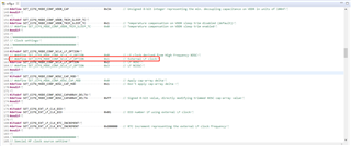
    Per our understanding, you can change the macro definition in the ccfg.c file as below showing:

    Hope it is usefu!

    BR./Zara Wu

  • Hi,

    Actually I have configured it already into

     #define SET_CCFG_MODE_CONF_SCLK_LF_OPTION            0x3        // LF RCOSC

    since I want to use the Internal RC oscillator instead of external LF OSC.

    Now I have issue with power consumption only.

  • Hi Ddnr,

    Application Report swra499c should contain all of the information you need to operate a low-power CC26XX project without the crystal.  That high of a power consumption implies that your device is staying in active mode and not entering standby, which will need to be further investigated.  Make sure you do not have an active JTAG connection and that your project is operating as expected while measuring the current.  Another document, swra478 may also help concerning this. 

    Regards,
    Ryan

  • Standby mode means low power mode. In low power mode we do have non-connectable advertisement (beacon, with 8sec interval). Would that be a cause?

    No JTAG connection is active, and functionality works as expected.

  • Hi Ryan,


    How can I check whether my device is still in Active mode and not entering standby?

    Note: In active mode, my device advertises is 1sec, but in standby mode my device is advertiseing with 8sec interval.....which are expected behaviour.

    Thanks. Expecting your reply and hints for investigation asap.

  • Standby mode should operate similarly concerning power usage between LF_XOSC and LF_RCOSC.  Do you still have the 8-second beacons when observing low current consumption using LF_XOSC?  How are you measuring power?  You can use the debugger to determine the state of your MCU and whether it is staying active or entering standby, it also appears as though the frequency of your advertisements is a clue.

    Regards,
    Ryan

  • Yes, from application side I can observe the 8sec advertisement (which is expected in low power mode) even in LF_RCOSC. But still the current is 1.8mA.

  • You should try verifying your setup with a default Bluetooth project and LaunchPad.

    Regards,
    Ryan

  • Hi Ryan,

    Thanks for the hint.

    I have verified using SimplePeripheral project and using Launchpad. Please find the following snapshot from power monitor tool (which I use for measurement). 

    Figure 1 - Advertising event current consumption 

    Figure 2 - Standby current consumption.

    I hope this is as expected ?

  • ~1 µA is expected for standby mode, if you are using a connection interval of 100 ms then your measurements appear to closely match expectations based on the Application Reports previously provided.

    Regards,
    Ryan

  • Thanks Ryan for verifying the result.

    May I know if there are chances of increase in Recharge pulses between advertising event.?

    According to the document, between 2 advertising event of 100ms, there is 1 recharge pulse. So if the advertising interval is 8seconds, how do we calculate the number of recharge pulse (fixed or dynamic) ?

    Background : When I test it with a different module, I observe the recharge pulses too frequently, and due to this the standby current is increasing.

    Thanks.

  • Recharge pulses are included in the expected standby current.  While the CC13x2 and CC26x2 have a built-in comparator that gives the optimal recharge interval at any time (and at any temperature), the recharge pulses are dynamically adapted based on the required time in Standby for the CC13x0 and CC26x0 devices. For the latter devices, the recharge interval will also depend on when in time the measurements are done with respect to the last reset of the DUT.  This is fully described in Section 2 of swra478.  If there is any difference between the board design of the two modules then you could compare these to further determine what differences could contribute to an increase in the standby current.

    Regards,
    Ryan

  • Ok.

    Could you please tell, what all clock registers i need to verify/check or is expected to change when we change from external 32kHz crystal to internal low frequency crystal. As below;

    If the low frequency clock is set to LF_RCOSC, then what is the expected value of :

    1. ACLK_REF_SRC_SEL -> (what is Aclk ref ?)

    00: RCOSC_HF derived (31.25kHz)
    01: XOSC_HF derived (31.25kHz)
    10: RCOSC_LF (32kHz)               ----------------??
    11: XOSC_LF (32.768kHz)

    2. SCLK_LF_SRC ->

    Indicates source for the sclk_lf
    0h = Low frequency clock derived from High Frequency RCOSC
    1h = Low frequency clock derived from High Frequency XOSC
    2h = Low frequency RCOSC ----------------------------??
    3h = Low frequency XOSC

    3. XOSC_LF_EN = 0

    4. RCOSC_LF_EN = 1

    Thanks

  • ACLK_REF_SRC_SEL and SCLK_LF_SRC_SEL are 0x00/RCOSC_HF by default.  XOSC_LF_EN is also disabled by default, and you can read all registers listed to verify their contents.  The correct configuration should be performed automatically by the MCU during start-up due to the CCFG setting.

    Regards,
    Ryan

  • Hi Ryan,

    Thanks for providing the info.

    I checked the registers and observed :

    ACLK_REF_SRC_SEL  = 0x0 (RCOSC_HF derived)

    SCLK_LF_SRC_SEL  = 0x2  (OSC_RCOSC_LF - which is different from what you have told)

    XOSC_LF_EN  = 0

    Why is the Aclk and Sclk Source different? And if it is not expected, how can I configure it correctly.

    Thanks.

  • I've stated the correct default reset values, the ones you've observed are a result of starting up the MCU with the CCFG feedback where SCLK_LF_OPTION is defaults at 0x03 = Low frequency RCOSC.  Hence the Using 32-kHz Crystal-Less Mode section of the BLE-Stack User's Guide.

    Regards,
    Ryan

  • OK

    Thanks.