This thread has been locked.

If you have a related question, please click the "Ask a related question" button in the top right corner. The newly created question will be automatically linked to this question.

LAUNCHXL-CC26X2R1: AoA inquiry

Part Number: LAUNCHXL-CC26X2R1

Hi Team,

This inquiry is a continuation of the other thread. https://e2e.ti.com/support/wireless-connectivity/bluetooth-group/bluetooth/f/bluetooth-forum/1127890/launchxl-cc26x2r1-aoa-inquiry

Here is the response of our customer.

Thank you for your response. Could you please explain more about what you mean by "Depending on the configuration selected, the answer to the first question may then be different."? In BOOSTXL antenna board, Antenna A2.1 can be turned on by just adding DIO28 using rtls_coordinatro example configuration file. In this way, I just used Antenna 0 with DIO28 and Antenna 1 with DIO29. Then I changed the python script antenna pattern to [0,1]. Each samples slot from antenna 0,1,0,1,0,1,.......
But I realized that this pattern is wrong. If I select antenna pattern as [0,1], then all the sample slots come from only antenna element 0 (correct me if I am wrong). So, I changed the pattern to [0,0,1].
All the calculations are done in the Matlab environment. At this stage, I do not worry about the multipath effect, since I first need to see at least some results in AoA values. Unfortunately, I am not getting the expected values for different angles.
Phase calculated as follows,
I = tbl.i; % collect the I values from the CSV file
Q = tbl.q; % collect the Q values from the CSV file
phase = rad2deg(atan2(I,Q));
Wavelength and AoA calculated as follows,
% calculating wavelnegth lambda
center_freq = 2402e+6 + channel_list*2e+6;
lambda = (3e+8)./center_freq;
D = 3.5e-2; % distance between two adjacent antennas

% calculating AoA
AoA = acosd( (phase_difference_packet.*lambda)/(2*pi*D) );
My results as follows (First column - phase difference, Second column - AoA)
I have attached two CSV files (filtered IQ values, Non-filtered IQ values) for your reference. If you can check (in case if you have your own algorithm) those, please let me know where I am wrong. Wrong with devices, Antenna configuration, my understanding, my Matlab script, or what?
Highly appreciate your work, you have helped me a lot so far.
Regards,
Danilo 
  • Hey Danilo,

    Thanks for posting on the forums. I will do my best to assist with this question, but please not our expert in this area is out of the office and will return next week. I will notify him of this thread upon his return.

    But I realized that this pattern is wrong. If I select antenna pattern as [0,1], then all the sample slots come from only antenna element 0 (correct me if I am wrong). So, I changed the pattern to [0,0,1].

    Can the customer verify the antenna assignments by using a logic analyzer on the appropriate antenna GPIO pin? Take a look at this section in the SimpleLink Academy Module: https://dev.ti.com/tirex/explore/content/simplelink_academy_cc13xx_cc26xxsdk_6_20_00_00/modules/rtls_toolbox_ble5/ble_aoa/ble_aoa_locator.html#step-2-ndash-verify-the-antenna-switching-pattern-used-by-the-locator 

    On the question regarding the data, I will have to defer this to my colleague for now. I will follow up next week.

  • Hi,

    Please review Ammar's suggestion to verify the antenna switching pattern.

    If I select antenna pattern as [0,1], then all the sample slots come from only antenna element 0 (correct me if I am wrong). So, I changed the pattern to [0,0,1].

    Pattern [0,1] looks correct to me, but you can verify this as suggested.

    center_freq = 2402e+6 + channel_list*2e+6;

    This is not totally correct but should have a limited impact on the results (see here).

    AoA = acosd( (phase_difference_packet.*lambda)/(2*pi*D) );

    I may have missed something, but this formula is not the one I expected. We have a lab discussing this.

    To finish, looking at the data in the screenshot, I am surprised the angle (second column) is a complex number (I expected a real number between -180 and +180).

    I hope this will help,

    Best regards,

  • Hi Clement,

    I just received this update from our customer.

    The problem was not solved. I do not have a digital analyzer but I check the antenna pattern using a oscilloscope. For the patter [1,2] it shows rectangular waveform with 4us on time and off time ( for 28pin).
    However, I get always 90 degrees as the AoA whatever the angle between the RX and TX.
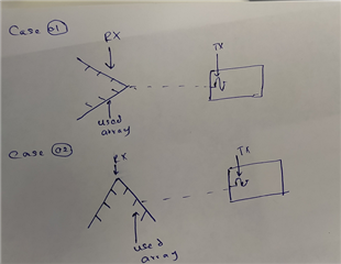
    Could you please tell me what should be the phase difference and angle of arrival for the cases described in the attachment.

    Regards,

    Danilo

  • Hi Danilo,

    Verifying the antenna switching pattern should be the priority here.Then, verify the antenna board is properly connected to the device's radio. Once this done, I recommend to verify the sanity of the IQ samples received by plotting the phase of the signals received by the two antennas on a graph.

    Best regards,