


Other Parts Discussed in Thread: OPT3001, FDC2214
Dear TI experts,
I designed a Devpack board that can communicate through I2C to CC2650stk. The devpack has been verified that data can be obtained by using Sensor Controller Studio.
I planned to implement the devpack data collection based on a example CCS Project sensortag_cc2650stk_app. Specifically, I modified the I2C address, register address and value in the SensorOpt3001.c source file, and then directly used the original OPT3001 related application and services to achieve the devpack data collection. The modified SensorOpt3001.c was posted below.
/*
 * Copyright (c) 2015-2016, Texas Instruments Incorporated
 * All rights reserved.
 *
 * Redistribution and use in source and binary forms, with or without
 * modification, are permitted provided that the following conditions
 * are met:
 *
 * *  Redistributions of source code must retain the above copyright
 *    notice, this list of conditions and the following disclaimer.
 *
 * *  Redistributions in binary form must reproduce the above copyright
 *    notice, this list of conditions and the following disclaimer in the
 *    documentation and/or other materials provided with the distribution.
 *
 * *  Neither the name of Texas Instruments Incorporated nor the names of
 *    its contributors may be used to endorse or promote products derived
 *    from this software without specific prior written permission.
 *
 * THIS SOFTWARE IS PROVIDED BY THE COPYRIGHT HOLDERS AND CONTRIBUTORS "AS IS"
 * AND ANY EXPRESS OR IMPLIED WARRANTIES, INCLUDING, BUT NOT LIMITED TO,
 * THE IMPLIED WARRANTIES OF MERCHANTABILITY AND FITNESS FOR A PARTICULAR
 * PURPOSE ARE DISCLAIMED. IN NO EVENT SHALL THE COPYRIGHT OWNER OR
 * CONTRIBUTORS BE LIABLE FOR ANY DIRECT, INDIRECT, INCIDENTAL, SPECIAL,
 * EXEMPLARY, OR CONSEQUENTIAL DAMAGES (INCLUDING, BUT NOT LIMITED TO,
 * PROCUREMENT OF SUBSTITUTE GOODS OR SERVICES; LOSS OF USE, DATA, OR PROFITS;
 * OR BUSINESS INTERRUPTION) HOWEVER CAUSED AND ON ANY THEORY OF LIABILITY,
 * WHETHER IN CONTRACT, STRICT LIABILITY, OR TORT (INCLUDING NEGLIGENCE OR
 * OTHERWISE) ARISING IN ANY WAY OUT OF THE USE OF THIS SOFTWARE,
 * EVEN IF ADVISED OF THE POSSIBILITY OF SUCH DAMAGE.
 */

/** ============================================================================
 *  @file       SensorOpt3001.c
 *
 *  @brief      Driver for the Texas Instruments OP3001 Optical Sensor.
 *  ============================================================================
 */

/* -----------------------------------------------------------------------------
*  Includes
* ------------------------------------------------------------------------------
*/
#include "Board.h"
#include "SensorOpt3001.h"
#include "SensorUtil.h"
#include "SensorI2C.h"
#include "math.h"

/* -----------------------------------------------------------------------------
*  Constants and macros
* ------------------------------------------------------------------------------
*/

/* I2C address */

#define Devpack_FDC2214_ADDR            0x54    //ADDR_Pin=VDD 0x56, ADDR_Pin=GND 0x54

/* FDC Register addresses */
// config
#define REG_CLOCK_DIVIDER_CH0           0x14
#define REG_CLOCK_DIVIDER_CH1           0x15
#define REG_CLOCK_DIVIDER_CH2           0x16

#define REG_CONFIG                      0x0A

#define REG_DRIVE_CURRENT_CH0           0x1E
#define REG_DRIVE_CURRENT_CH1           0x1F
#define REG_DRIVE_CURRENT_CH2           0x20

#define REG_ERROR_CONFIG                0x19
#define REG_MUX_CONFIG                  0x1B

#define REG_RCOUNT_CH0                  0x08
#define REG_RCOUNT_CH1                  0x09
#define REG_RCOUNT_CH2                  0x0A

#define REG_SETTLECOUNT_CH0             0x10
#define REG_SETTLECOUNT_CH1             0x11
#define REG_SETTLECOUNT_CH2             0x12

// result
#define REG_DATA_CH0_LSB                0x01
#define REG_DATA_CH0_MSB                0x00

//ID
#define REG_MANUFACTURER_ID             0x7E
#define REG_DEVICE_ID                   0x7F

/* FDC Register values (little endian) */
// config
#define CLOCK_DIVIDER_CH0               0x2002
#define CLOCK_DIVIDER_CH1               0x2002
#define CLOCK_DIVIDER_CH2               0x2002

#define CONFIG_ENABLE                   0x1601  // active mode
#define CONFIG_DISABLE                  0x2801  // sleep mode

#define DRIVE_CURRENT_CH0               0x7C00
#define DRIVE_CURRENT_CH1               0x7C00
#define DRIVE_CURRENT_CH2               0x7C00

#define ERROR_CONFIG                    0x0000
#define MUX_CONFIG                      0xC20D

#define RCOUNT_CH0                      0x8329
#define RCOUNT_CH1                      0x8329
#define RCOUNT_CH2                      0x8329

#define SETTLECOUNT_CH0                 0x000A
#define SETTLECOUNT_CH1                 0x000A
#define SETTLECOUNT_CH2                 0x000A

// ID
#define MANUFACTURER_ID                 0x5449
#define DEVICE_ID                       0x3055

/* Bit values */
//#define DATA_RDY_BIT                    0x8000  // Config: 0x0080 = Data ready

/* Register length */
#define REGISTER_LENGTH                 2

/* Sensor data size */
#define DATA_LENGTH                     2

// FDC Sensor selection/de-selection
#define SENSOR_SELECT()     SensorI2C_select(SENSOR_I2C_0,Devpack_FDC2214_ADDR)
#define SENSOR_DESELECT()   SensorI2C_deselect()

/* -----------------------------------------------------------------------------
*  Public functions
* ------------------------------------------------------------------------------
*/

/*******************************************************************************
 * @fn          SensorOpt3001_init -> Fdc2214_init
 *
 * @brief       Initialize the temperature sensor driver
 *
 * @return      none
 ******************************************************************************/
bool SensorOpt3001_init(void)
{
    SensorOpt3001_enable(false);

    return true;
}

/*******************************************************************************
 * @fn          SensorOpt3001_enable -> Fdc2214_enable
 *
 * @brief       Turn the sensor on/off
 *
 * @return      none
 ******************************************************************************/
void SensorOpt3001_enable(bool enable)
{
    uint16_t val, val_config;

    if (!SENSOR_SELECT())
    {
        return;
    }

    if (enable)
    {
        val = CONFIG_ENABLE;
    }
    else
    {
        val = CONFIG_DISABLE;
    }

    val_config = CLOCK_DIVIDER_CH0;
    SensorI2C_writeReg(REG_CLOCK_DIVIDER_CH0, (uint8_t *)&val_config, REGISTER_LENGTH);

    val_config = DRIVE_CURRENT_CH0;
    SensorI2C_writeReg(REG_DRIVE_CURRENT_CH0, (uint8_t *)&val_config, REGISTER_LENGTH);

    val_config = SETTLECOUNT_CH0;
    SensorI2C_writeReg(REG_SETTLECOUNT_CH0, (uint8_t *)&val_config, REGISTER_LENGTH);

    val_config = RCOUNT_CH0;
    SensorI2C_writeReg(REG_RCOUNT_CH0, (uint8_t *)&val_config, REGISTER_LENGTH);

    val_config = ERROR_CONFIG;
    SensorI2C_writeReg(REG_ERROR_CONFIG, (uint8_t *)&val_config, REGISTER_LENGTH);

    val_config = MUX_CONFIG;
    SensorI2C_writeReg(REG_MUX_CONFIG, (uint8_t *)&val_config, REGISTER_LENGTH);

    SensorI2C_writeReg(REG_CONFIG, (uint8_t *)&val, REGISTER_LENGTH);


    SENSOR_DESELECT();
}

/*******************************************************************************
 * @fn          SensorOpt3001_read -> Fdc2214_read
 *
 * @brief       Read the result register
 *
 * @param       Buffer to store data in
 *
 * @return      true if valid data
 ******************************************************************************/
bool SensorOpt3001_read(uint16_t *rawData)
{
    bool success;
    uint16_t val;

    if (!SENSOR_SELECT())
    {
        return false;
    }

    success = SensorI2C_readReg(REG_DATA_CH0_MSB, (uint8_t *)&val, DATA_LENGTH);

    if (success)
    {
        // Swap bytes
        *rawData = (val << 8) | (val>>8 &0xFF);
    }

    SENSOR_DESELECT();

    return success;
}

/*******************************************************************************
 * @fn          SensorOpt3001_test
 *
 * @brief       Run a sensor self-test
 *
 * @return      true if passed
 ******************************************************************************/
bool SensorOpt3001_test(void)
{
    uint16_t val;

    // Select this sensor on the I2C bus
    if (!SENSOR_SELECT())
    {
        return false;
    }

    // Check manufacturer ID
    ST_ASSERT(SensorI2C_readReg(REG_MANUFACTURER_ID, (uint8_t *)&val, REGISTER_LENGTH));
    ST_ASSERT(val == MANUFACTURER_ID);

    // Check device ID
    ST_ASSERT(SensorI2C_readReg(REG_DEVICE_ID, (uint8_t *)&val, REGISTER_LENGTH));
    ST_ASSERT(val == DEVICE_ID);

    SENSOR_DESELECT();

    return true;
}

/*******************************************************************************
 * @fn          SensorOpt3001_convert
 *
 * @brief       Convert raw data to LUX
 *
 * @param       rawData - raw data from sensor
 *
 * @return      lux - converted value (lux)
 *
 ******************************************************************************/
float SensorOpt3001_convert(uint16_t rawData)
{
    uint16_t e, m;

    m = rawData & 0x0FFF;
    e = (rawData & 0xF000) >> 12;

    return m * (0.01 * exp2(e));
}
After the modification, there was no error after build, but when I checked the data through the IOS APP, the data shown in the original OPT3001section was always 0000.
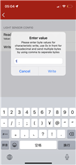
I tried to enable the sensor in the app's Service Explorer, but it failed. The result is as shown below. Does this mean the device is not recognized?


So, what other files need to be modified? Or is there a problem with my code?
In addition, how to map and configure pins in CCS Project sensortag_cc2650stk_app to achieve configuration such as the sensor controller below?
Because DEVPACK requires CC2650STK's DP1 (DIO24) to be set to logic 0, and DP2 (DIO23) and DP3 (DIO27) to be set to logic 1. DIO6 and DIO 5 should be configure as SCL and SDA.


Best regards,
Will

