This thread has been locked.

If you have a related question, please click the "Ask a related question" button in the top right corner. The newly created question will be automatically linked to this question.

the antenna and the RF application of CC2530

Other Parts Discussed in Thread: CC2530, CC2530EM

i design an application of CC2530 recently.
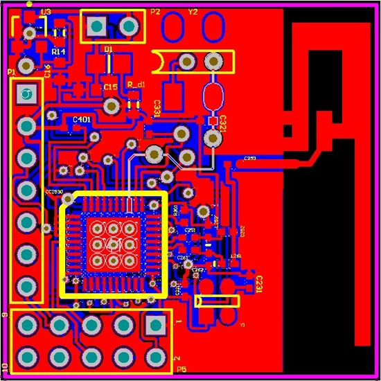
 

in my application ,i use the usart(in uart model)to recive number and send it to the air by the rf.

i have configured that the I/0 and the UART is right. but the rf isn' working.


my question is :

(1)is my RFdesign is right(two inductor which value is 2nH,i use 1.8nH to instead.)

(2) how to debug my rf part of my application.


  • Hi,

    The slight variation in inductance might be okay. But there are multiple factors that contribute to the impedance of the RF matching.

    Things like the:
    1. board stacking height
    2. length of traces between components
    3. material dielectric
    4. layout of the board itself (one always wants to be as symmetric as possible, as any asymmetry will cause an impedance mismatch at 2.4GHz)
    5. ground plane should be solid under the RF with no routing right under

    Factors like these dictate how well the matching network will work, there by allowing for max power transfer.

    That is why we stress that people follow the reference design as closely as possible so as to get the best possible results.

    I am not sure by what you mean by debug the RF part. If you mean tuning the matching network. If so, you'd need a Network Analyzer to measure the impedance as seen by the different parts of the RF path and try to make the best match possible by varying component values. Thing to remember; the impedance out the RF matching network should be equal to the impedance seen at the antenna for max power transfer.

  • thanks for your reply. i have learnt a lot.

    my point is only to achieve a goal of finish a wireless communication module. this module recieve number form the UART and send it to the air. i have finished the soft ware in an konwn hardware.what i have do is copy what i need .but when i test if it working in the right way,i just find the USART is right.and the RF part isn't working .

    the meaning of debug the  RF part means debug the hard ware(the MCU ,the balun net work and the antenna);and the soft ware in the MCU(2530).

    my problem is how do i know what condition the hareware is working on. must I use the network analyzer? i was just a undergraduate student and my major isn;t about wireless communication. that's the problem.


    and how to debug the soft ware of the zigbee controller?what i know is only to read the memorizer about the zigbee.


    thanks a lot!

  • Hi Ming,

    I would redo the layout of the balun if I were you. You should try to replicate the layout of the CC2530EM reference design as closely as possible. It is not only the component values that determines how well your RF circuit will work, but also the placement of the components and the dimensions of the traces and distance to ground. You could also mirror the antenna to avoid the long horizontal trace (vertical in the image). Use google to find a free microstrip calculator and make sure your RF traces have 50 ohm impedance. On the bottom layer, there should be no traces underneath the RF circuit.

    One way to "debug" the RF part is to solder a semi regid coax cable to the pad of the last capacitor before the antenna (remove the cap, so the antenna is disconnected) and measure how much power you are getting through the balun/filter.

    /Fredrik

  • oh,my god. in my PCB board ,there is traces right under the balun part. and my balun part isn;t as same as  the official design(the CC2530EM).

    i want resue the design by taking this measures,isn;t it will work?

    1.there's traces right under the balun part, if i use the Network Analyzer  to measure the independence and change the components value,will it work?

    2.if 1will not work,can i scrape the traces under the balun and connectted with the real wire ?( there are three lines ,one is ground line and the other two is debug +and debug-,without the debug _+ and debug_-,it will not influnce it's work. )

    3.the datasheet want the antenna's independece is 50 ohm,but it depends on the material and the thickness. is it must be equal to 50ohm  or just make the balun and the antenna match and it will OK?

    thanks a lot.


  • and i take these measures for the purpose to make my model is available, even it's performance is very bad,only if it can be used for basic experiment.and the distance it can transduce,i don;t care in this moment. 

  • Hi Ming,

    If you want good RF performance you should redo the design completely. If you just want somethint to test on your desk at the moment, the design you have already made will probably do the job.

    1. The problem here is not so match the impedance, but rather leakage from the digital signal to the RF lines.

    2. Yes you could replace the traces with straps.

    3. The easiest solution here is to replicate TIs reference design, and make sure the trace between the antenna and balun is close to 50 ohm. You can use an online microstrip calculator for the latter.


    F

  • thanks very much for your guidance in the rf.

    but i just can't learn your mean accurrately.


    in fact ,i have weld the components  to the PCB board. and i test the basic I/O,the timer ,the crystal ,and the  UART .they work well.but the RF is not.

    i download the program which i have tested  in annother hardware  to the board. (the program is to recieve data from the uart and send it to the air,and in the already_hardware,it work;both the already hard ware and my design hard ware share the same defination of hardware such as i/o.) but the rf isn;t work. my god.

    i think maybe the RF part is wrong. because as you have said, i didn't do the same as the reference design. and what i want ,is to make the rf work.

    for this purpose:

    i have to:make my board as similar with the refrence design as possible.

    1.i have to make sure that the independence of the antenna is 50ohm,from the last capatitor  to the point which the antenna get touch with the GND,but the board has been done,so ,i can just measure its independence and cannot change it?

    2. the independence of the balun ,it means  from the capatitor C253(which connected to the antenna),i will see the independence is about 50ohm? in my case ,i should make it as close to 50ohm as possible or as the same as the antenna. the material is FR-4.

    3.i didn;t know the mean the leakage ,is it will make the energy loose from the main  frequency  to the frequncy to other? and how can i solve it?

    the rf

  • Ming,

    Unfortunately the only solution for you right now is to try an redo the RF part. But since the board is made already and it's not symmetrical trying to match the impedance from the RF_P and RF_N ports of the chip to the antenna might be extremely difficult. Usually we suggest to customers who have already made boards, to vary their component values to make the impedance seen from the antenna side looking into the board the same as the impedance looking from the board side to the antenna. Usually wwe suggest that they make the impedance for the balun and antenna be 50ohms. But if you can match them to another value, its okay, as long as you can match it.

    Also, sorry to be the bearer of bad news here, RF is complicated, miss match in the path, especially the way you have it will cause impedance mismatch that will attenuate the power and in your case cause your RF to fail.

    Can you try bringing both board close to each other and see if there is any pick up? Also, sometimes the soldering or routing of the board is incorrect which leads to some parts simply not working. Can you verify connection once again. Have you been able to measure the impedance of the balun or the antenna? 

    Another thing, the fact that you have so many digital lines crossing the RF path. The cause the RF return path to be obsturcted. This will cause further issues.