This thread has been locked.

If you have a related question, please click the "Ask a related question" button in the top right corner. The newly created question will be automatically linked to this question.

CC2652R7: ADC Compensation

Part Number: CC2652R7

Customer have CC2652R7  ADC measuring across a 1V range for vehicle voltage, 12/24 volt operation, and the voltage ratio to measure is 30.4:1, across 1V reference.  On one device, the see that this conversion of slope of 30.4:1 works fine, and there is 0 offset.


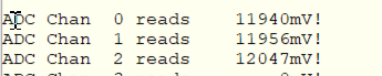
At 12 volts, it look great on all three points of measurement, and tracks well at 10 and 20V settings.


However, measurements from 3 other boards measure 12.4, 11.1, and 10.9V with the same FW.   The slope looks good, but there is clearly an offset.


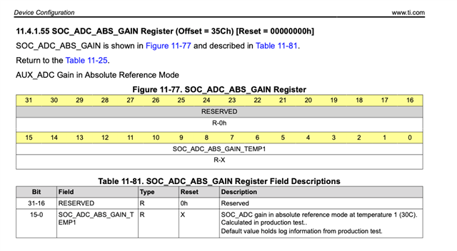
They are looking at the CC2652 documentation, at some compensation registers.  Do we have to use these values to compensate? And why are then 0 at reset?


They are using the below API’s.


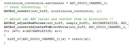
Any suggestions as to why I am seeing this offset and how to compensate?

  • Hi Lawrence,

    The ADCBuf functions (TI Drivers Runtime APIs) should compensate accordingly. Which SimpleLink SDK version are they evaluating and would they be able to specify the changes applied to adcbufcontinous to observe this behavior?  Are they using the fixed reference source (default) and monitoring the input voltage to ensure that it is exactly as expected and does not exceed the SimpleLink device limitations?

    Regards,
    Ryan

  • Attached is modified ADCBufContinuous example

    /*
     * Copyright (c) 2015-2021, Texas Instruments Incorporated
     * All rights reserved.
     *
     * Redistribution and use in source and binary forms, with or without
     * modification, are permitted provided that the following conditions
     * are met:
     *
     * *  Redistributions of source code must retain the above copyright
     *    notice, this list of conditions and the following disclaimer.
     *
     * *  Redistributions in binary form must reproduce the above copyright
     *    notice, this list of conditions and the following disclaimer in the
     *    documentation and/or other materials provided with the distribution.
     *
     * *  Neither the name of Texas Instruments Incorporated nor the names of
     *    its contributors may be used to endorse or promote products derived
     *    from this software without specific prior written permission.
     *
     * THIS SOFTWARE IS PROVIDED BY THE COPYRIGHT HOLDERS AND CONTRIBUTORS "AS IS"
     * AND ANY EXPRESS OR IMPLIED WARRANTIES, INCLUDING, BUT NOT LIMITED TO,
     * THE IMPLIED WARRANTIES OF MERCHANTABILITY AND FITNESS FOR A PARTICULAR
     * PURPOSE ARE DISCLAIMED. IN NO EVENT SHALL THE COPYRIGHT OWNER OR
     * CONTRIBUTORS BE LIABLE FOR ANY DIRECT, INDIRECT, INCIDENTAL, SPECIAL,
     * EXEMPLARY, OR CONSEQUENTIAL DAMAGES (INCLUDING, BUT NOT LIMITED TO,
     * PROCUREMENT OF SUBSTITUTE GOODS OR SERVICES; LOSS OF USE, DATA, OR PROFITS;
     * OR BUSINESS INTERRUPTION) HOWEVER CAUSED AND ON ANY THEORY OF LIABILITY,
     * WHETHER IN CONTRACT, STRICT LIABILITY, OR TORT (INCLUDING NEGLIGENCE OR
     * OTHERWISE) ARISING IN ANY WAY OUT OF THE USE OF THIS SOFTWARE,
     * EVEN IF ADVISED OF THE POSSIBILITY OF SUCH DAMAGE.
     */
    /*
     *  ======== adcBufContinuousSampling.c ========
     */
    #include <stdint.h>
    #include <stdio.h>
    #include <mqueue.h>
    
    /* Driver Header files */
    #include <ti/drivers/ADCBuf.h>
    #include <ti/drivers/GPIO.h>
    
    /* Display Header files */
    #include <ti/display/Display.h>
    
    /* Driver configuration */
    #include "ti_drivers_config.h"
    
    #define ADCSAMPLESIZE    (50)
    #define ADCSAMPLERATE    (200)
    #define MAX_QUEUED_ADC_CONVERSIONS (4)
    #define QUEUED_ADC_MESSAGE_SIZE (sizeof(uint32_t) * ADCSAMPLESIZE)
    
    uint16_t sampleBufferOne[ADCSAMPLESIZE];
    uint16_t sampleBufferTwo[ADCSAMPLESIZE];
    uint32_t microVoltBuffer[ADCSAMPLESIZE];
    uint32_t outputBuffer[ADCSAMPLESIZE];
    uint32_t buffersCompletedCounter = 0;
    
    /* Display Driver Handle */
    Display_Handle displayHandle;
    
    /* Used to pass ADC data between callback and main task */
    static mqd_t queueReceive;
    static mqd_t queueSend;
    
    /*
     * This function is called whenever an ADC buffer is full.
     * The content of the buffer is then converted into human-readable format and
     * sent to the main thread.
     */
    void adcBufCallback(ADCBuf_Handle handle, ADCBuf_Conversion *conversion,
        void *completedADCBuffer, uint32_t completedChannel, int_fast16_t status)
    {
        /* Adjust raw ADC values and convert them to microvolts */
        ADCBuf_adjustRawValues(handle, completedADCBuffer, ADCSAMPLESIZE,
            completedChannel);
        ADCBuf_convertAdjustedToMicroVolts(handle, completedChannel,
            completedADCBuffer, microVoltBuffer, ADCSAMPLESIZE);
    
        /* Send ADC data to main thread using message queue */
        mq_send(queueSend, (char *) microVoltBuffer, QUEUED_ADC_MESSAGE_SIZE, 0);
    }
    
    /*
     *  ======== mainThread ========
     */
    void *mainThread(void *arg0)
    {
        Display_Params displayParams;
        ADCBuf_Handle adcBuf;
        ADCBuf_Params adcBufParams;
        ADCBuf_Conversion continuousConversion;
        struct mq_attr attr;
        uint32_t average;
        uint_fast16_t i = 0;
    
        /* Create RTOS Queue */
        attr.mq_flags = 0;
        attr.mq_maxmsg = MAX_QUEUED_ADC_CONVERSIONS;
        attr.mq_msgsize = QUEUED_ADC_MESSAGE_SIZE;
        attr.mq_curmsgs = 0;
    
        queueReceive = mq_open("ADCBuf", O_RDWR | O_CREAT, 0664, &attr);
        queueSend = mq_open("ADCBuf", O_RDWR | O_CREAT | O_NONBLOCK, 0664,
                              &attr);
        if ((queueReceive == (mqd_t)-1) || (queueSend == (mqd_t)-1)) {
            /* Failed to open message queue */
            while (1);
        }
    
        /* Call driver init functions */
        ADCBuf_init();
        Display_init();
        GPIO_init();
    
        /* turn on switched power */
        GPIO_setConfig(CONFIG_SW_EN, GPIO_CFG_OUT_STD | GPIO_CFG_OUT_HIGH);
        GPIO_write(CONFIG_SW_EN, 1);
    
        /* Configure & open Display driver */
        Display_Params_init(&displayParams);
        displayParams.lineClearMode = DISPLAY_CLEAR_BOTH;
        displayHandle = Display_open(Display_Type_UART, &displayParams);
        if (displayHandle == NULL) {
            Display_printf(displayHandle, 0, 0, "Error creating displayHandle\n");
            while (1);
        }
    
        Display_printf(displayHandle, 0, 0,
                        "Starting the ADCBufContinuous example");
    
        /* Set up an ADCBuf peripheral in ADCBuf_RECURRENCE_MODE_CONTINUOUS */
        ADCBuf_Params_init(&adcBufParams);
        adcBufParams.callbackFxn = adcBufCallback;
        adcBufParams.recurrenceMode = ADCBuf_RECURRENCE_MODE_CONTINUOUS;
        adcBufParams.returnMode = ADCBuf_RETURN_MODE_CALLBACK;
        adcBufParams.samplingFrequency = ADCSAMPLERATE;
        adcBuf = ADCBuf_open(CONFIG_ADCBUF_0, &adcBufParams);
    
        /* Configure the conversion struct */
        continuousConversion.arg = NULL;
        continuousConversion.adcChannel = CONFIG_ADCBUF_0_CHANNEL_0;
        continuousConversion.sampleBuffer = sampleBufferOne;
        continuousConversion.sampleBufferTwo = sampleBufferTwo;
        continuousConversion.samplesRequestedCount = ADCSAMPLESIZE;
    
        if (adcBuf == NULL){
            /* ADCBuf failed to open. */
            while(1);
        }
    
        /* Start converting. */
        if (ADCBuf_convert(adcBuf, &continuousConversion, 1) !=
            ADCBuf_STATUS_SUCCESS) {
            /* Did not start conversion process correctly. */
            while(1);
        }
    
        /*
         * Wait for the message queue to receive ADC data from the callback
         * function. When data is received, calculate the average and print to UART
         */
        while(1) {
            if (mq_receive(queueReceive, (char *) outputBuffer,
                           QUEUED_ADC_MESSAGE_SIZE, NULL) == -1)
            {
                Display_printf(displayHandle, 0, 0, "Error receiving ADC message");
                while(1);
            }
    
            Display_printf(displayHandle, 0, 0, "Buffer %u finished:",
                        (unsigned int)buffersCompletedCounter++);
    
            /* Calculate average ADC data value in uV */
            average = 0;
            for (i = 0; i < ADCSAMPLESIZE; i++) {
                average += outputBuffer[i];
            }
            average = average/ADCSAMPLESIZE;
            /* scale */
            average = average * 31;
            average = average / 1024;
    
            /* Print average ADCBuf value */
            Display_printf(displayHandle, 0, 0, "  Average: %u uV", average);
        }
    }
    

    ADC Results from 2 difference boards

    ADC Results.xlsx

    Looking for suggestion to have a more consistent result

  • What SDK version are they using and are results more consistent without the additional average scaling math operations?  What input voltage levels are directly provided to the SimpleLink GPIO pin and have they carefully measured each board's hardware to ensure that each is identical?  Between ADC characteristics listed in the datasheet, hardware variation, and additional integer math, it is possible to deviate from the desired measurement results.  They could also try to increase the samplingDuration through custom parameters as shown in ADCBufCC26X2.

    Regards,
    Ryan

  • They are using Simple link 5.40.00.40.  I will get the other information you requested from them.