This thread has been locked.

If you have a related question, please click the "Ask a related question" button in the top right corner. The newly created question will be automatically linked to this question.

CC2650: antenna feed design

Part Number: CC2650

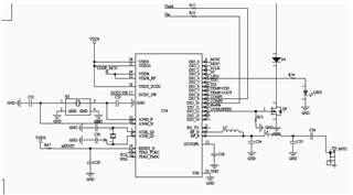
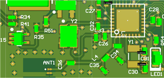
I am working with a CC2650 on a PCB I designed and I am not seeing the expected TX power; I have a single-ended antenna feed based (approximately) on the reference design in the datasheet, and I believe I have the radio set up for max power. However, when I look at the advertising packets they seem to be at about -3 dBm. I am measuring with a 50 Ohm 6 GHz scope in place of the antenna. 

I suspect the problem may be with my antenna feed, and I am thinking to build a separate one to the same design and test it with a VNA. However, I can't find any information about what impedance the CC2650 expects to see at the antenna feed input. Is this information documented somewhere?  

Thanks for any help you can offer.

  • Hi,

    Even if the antenna feed is far from 50 ohms you should still see better conducted output power when programmed to maximum than -3 dBm.

    Suspect that the passive components are incorrect in the RF path.

    Can you share your schematic and layout ?

    Regards,

       Richard

  • Hi, thanks for getting back to me. I am attaching images of the relevant schematic and PCB areas.

    The antenna feed components I have are:

    C34 = C35 = 1.2 pF; C36 = 12 pF; L3 = 15 nH; L4 = 2 nH; all 0402.

    In place of the chip antenna I currently have a surface mount UFL socket.

    The board is a Polyimide flex PCB. If I remember correctly the PI is ~100 um thick and the Cu is 1 oz. There is ground plane behind the antenna feed circuit. 

    Thanks

  • Hi,

    You should be measuring around +2 dBm when using single-ended on CC2650 so there's 5 dBs missing. 

    Make sure you are testing with the Front-end configured as External Bias, Single-ended RF on RFP:

    What conducted output power do you measure with this setting? 

  • Hi, thanks for this. I am not sure about the front-end configuration but will check. It looks as though this is a setting in the IDE rather than something we need to initialise at run time - is that correct? (Sorry for the naive question but someone else has done all the coding on this project.)

  • Hi,

    Please check the front-end setting since the default for the radio is normally External Bias and Differential so this could be one source of the poor output power. This is a setting that initializes the radio between operating in a differential mode or single-ended mode. Since your hardware is based upon single-ended, then this has to be similarly configured in your firmware. 

  • Hi Richard, sorry for all the dumb questions, but can you tell me how to bring up the Custom Target Configuration window you included in your screenshot? We have been looking under Target Configuration but haven't been able to locate it. (If it is relevant, the device we are working with is the CC2650F128 (5x5). ) Many thanks.

  • Hi,

    No problems.

    Download SmartRF studio: https://www.ti.com/tool/SMARTRFTM-STUDIO

    Double click on CC2650 (it should be highlighted if you have a board connected)

    Select: BLE Mode for example

    Press on the Customize button (top right), then this will bring up the  Custom Target Configuration Window: