i team,
Here's the request from the customer:
Developing with CC2642R and SDK version is 6.40. The example is simple_peripheral and the board is to use the official development board.
Customer lets SPI act as the SLAVE role, and it will be in the Shutdown state under normal conditions. And use the cs pin as Wakeup.
This all goes well and also communicates and read values correctly.
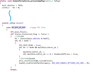
But when the SPI receives a specified COMMAND, it can no longer SHUTDOWN.
Remain in STANDBY state and continue to listen to the SPI communication.
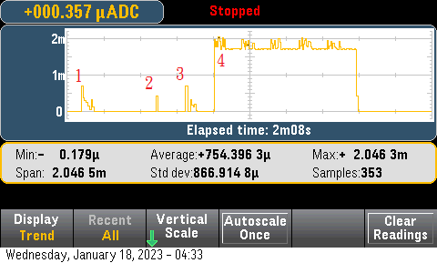
The question is here, why the power consumption in STANDBY mode jumps from uA to mA and remains?
(The hardware is completely free of additional peripheral I/O usage, and the UART is also DISABLE)
As shown below:
Supplementary Note::
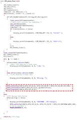
At the end of SPI communication FUNCTION, if it does not enter POWER DOWN, then execute the following references.
GPIO_init();
GPIO_setConfig(CONFIG_GPIO_SPI_0_SS, GPIO_CFG_IN_PU | GPIO_CFG_IN_INT_FALLING);
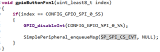
GPIO_setCallback(CONFIG_GPIO_SPI_0_SS, gpioButtonFxn1);
GPIO_enableInt(CONFIG_GPIO_SPI_0_SS);
It is also here that the power consumption increases.
Could you help check this case? Thanks.
Best Regards,
Nick