This thread has been locked.

If you have a related question, please click the "Ask a related question" button in the top right corner. The newly created question will be automatically linked to this question.

CC2652P7: Does Radio Test Library support CC2652P7?

Part Number: CC2652P7
Other Parts Discussed in Thread: CC1352P7, CC2652R

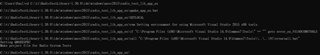
A customer is trying to use the radio test library 1.30 from SmartRF Studio 7 to control CC2652P7 for RF test, but it seems there is no CC2652P7 in the device name list:

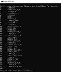
Do we have to modify the source code to add the support for CC2652P7?

There's another question, the customer's board uses different pins for antenna switch, how to control the antenna switch pins through radio test library?

Best regards,

Shuyang

  • Hi Shuyang,

    Has the customer tried using the CC1352P7_BLE or CC1352P7_IEEE_15_4 settings on their CC2652P7 device?  These should be functionally equivalent and binary compatible for 2.4 GHz solutions.

    Regards,
    Ryan

  • Hi Ryan,

    Thanks for the useful advice, the customer has confirmed that CC1352P7_IEEE_15_4 setting works.

    Can you please also comment on the antenna switch question? Is it possible to use radio test library to control a custom antenna switch pin? 

    BR,

    Shuyang

  • Hi Shuyang,

    I apologize as I hadn't seen the second question.  Assuming main.cpp defaults to targetBoard = LP_CC1352P7-4 in setTargetBoardAndGetTxPowerValue, the RadioTestLibrary-1.30.0\config\xml\cc1352p7\targets\targets.xml appears to still reference target_launchxl-cc1352p7-4_highPA.xml, which is where the RF Switch pins are defined.  I would recommend rebuilding the rtlib project so that LP-CC1352P7-2 (20 dBm) or LP-CC1352P7-4 (10 dBm) specific *.xml is selected for 2.4 GHz high PA operation.  I will ask the Tools Team to confirm this.

    Regards,
    Ryan

  • Information from the Tools Team:

    The CC2652P7 is supported by RTLib but you don’t find the device in the code examples provided together with the library. The thinking is that it should be sufficient to enable users to create testing for other devices as well.

    In the code examples you will find a function call getTargetName(). This name is referring to the name you see in the dropdown of RF Designs in SmartRF Studio. The same name can be found in the targets.xml file. Here it is called a “VirtualTarget” since it have two actual target definitions depending on if it is with “High PA” or not.  For 2.4 it is either LP_CC1352P7-2 or -4 that is used. The xml file for each target is given here.

    Inside the target definition you have the settings for the IO pins depending on the required control signals for the antenna switch.  This file also contain a tag called “PaSettings”. This points to the TX power settings file. The file can be found on the “..\pa_tables” folder.  The PA Table to use is depending on the “RfDesign”, given in the target file, and the frequency range.

    There is an option to create “custom boards” in the GUI version but for use together with RTLib it is probably just as easy to create new xml files directly in the file structure of the installed SmartRF Studio. That also means that it makes everything much easier if SmartRF Studio is installed somewhere else than under the default “Program files” folder. This folder makes it more difficult to update and copy files because of the limited access permission.

    If it is not required to differentiate between using the “High PA” option or not, the VirtualTarget tag doesn’t need to be used. Then the Target tag can be used. Look at CC2652R as an example.  If you need PA table  for both “High PA” and “Normal PA”, then the difference is seen by the tool from the name used in the target definition. For example “LP_CC1352P7-HIGH-PA” and “LP_CC1352P7”.  There is a function called setTargetBoardAndGetTxPowerValue() that show how the “targetboard” and the “txPowerHighPa” parameter is set. When “txPowerHighPa” is true, the “HIGH-PA” variant will be used.

    Regards,
    Ryan

  • Hi Ryan,

    Thanks for the detailed answer. I managed to create a custom setting file by changing the DIO setting in target_launchxl-cc1352p7-4_highPA.xml.

    But there is a problem: the customer is using the power table of 20dBm, but in setTargetBoardAndGetTxPowerValue() the tx power will be set to 10dBm. Is there a way to change the tx power to 20dBm without recompiling the project? The project is built with MSVC 2015 but I do not have access to this IDE.

    Best regards,

    Shuyang

  • Hi Shuyang,

    I believe a recompile is required for effective 20 dBm use of the CC1352P7 with radio_test_lib_app executable.  I will have the Tools Team confirm this.

    Regards,
    Ryan

  • Hi Ryan,

    Did you get the feedback from the tools team? I tried to recompile the radio_test_lib_app but failed, looks it depends on the QT which I'm not familiar with, I might need some help from the tools team to rebuild this project, thanks.

    BR,

    Shuyang

  • I have not heard back and am checking in with them.  Have you downloaded/installed the QT source files and would you be able to provide more information on the compile issue you are experiencing?

    Regards,
    Ryan

  • Yes I downloaded the QT installer package and was able to generate the project file through qmake_app_ex.bat. Below is the script log:

    Then I opened the project with Visual Studio 2015 Express and tried to rebuild it, got the errors as below:

    The error "expected a file name" points to statement like this:

    #if QT_HAS_INCLUDE(<chrono>)

    How to fix this?

    Best regards,

    Shuyang

  • Thanks Shuyang, did you run the qmake_app_ex.bat from the command window that is provided on the Windows Start-up menu by Qt?  This appears to be an important step from the RTLib documentation.  I will ask the Tools Team to review and comment.

    Regards,
    Ryan

  • The Tools Team has confirmed that their setup still operates as expected.  They have suggested to ensure that the 32-bit option of the command window is selected when running qmake_app_ex.bat since the 64-bit version will not work with existing Smart RF Studio resources.

    Regards,
    Ryan