This thread has been locked.

If you have a related question, please click the "Ask a related question" button in the top right corner. The newly created question will be automatically linked to this question.

CC2652R7: technical problem

Part Number: CC2652R7
Other Parts Discussed in Thread: , SYSCONFIG, ENERGYTRACE

Hi team,

I help my customer to ask a question.

the issue is how to put cc2652r7 to different modes(standby, shutdown etc), using btool, why when im connecting the mode to btool with custom settings, it shows "Device reset timed out Device may not function properly?

Thank you very much for your help.

Best regards,

  • Hi,

    The BTool software is intended to be used with the host_test project or a PTM-enabled project. In both cases, the device should be using a BLE project and in BLE projects the Power Manager takes care of placing the device in the lowest power mode possible at any given time. We will consider the case where host_test is being used, but this information is applicable to PTM enabled projects.

    Host_test uses the NPI to communicate between the IC and an external device. By default, host_test uses NPI via UART. As stated in the CC265R7 datasheet in Table 8-1. In order to go down to standby or shutdown, the device must have closed all peripherals. Thankfully, NPI is able to take care of this for us. NPI can be implemented in UART or SPI and through the use of the POWER_SAVING pre-define and the MRDY/SRDY signals, the peripherals can be shutdown and activated as needed which allows the device to go into standby whenever possible. There is information on how to do this in the previously linked NPI chapter.

    The "Device reset timed out Device may not function properly" appears when the device resets or btool does not receive an expected response from the device. When this occurs, the device should be reset via btool with the HCIExt_ResetSystemCmd command. This command will reset the IC and resync the UART communication. Afterwards, any command should be able to be sent such as GapDevice_init(). 

    I believe the gpioStandby and gpioShutdown example may be a valuable reference for the customer as these examples provide information on how to shutdown the device and how to go into standby. For standby, the power manager should take care of this, but to make the device go into shutdown, then one must instruct it to do so and the gpioShutdown example shows this process.

    Best Regards,

    Jan

  • Btool is not responding to the code HCIExt_ResetSystemCmd command either it shows "send Command Failed Message Name = GATT_WriteLongVhatValue" , how to rectify this and (can we) put Lp cc2652R7 in different modes like shutdown, sleep etc and also different modes for different modules like BTstandby, ZigBee standby etc

  • Hi,

    Is the host_test example flashed onto the LP-CC2652R7 device? The host_test image or a PTM enabled image is required for btool functionality.

    Best Regards,

    Jan

  • Hi Jan,

    Thank you for your help.

    Arun is my end customer,today he is unable to post a reply.so I help to do it.

    "Still after flashing host_example I'm getting "Reset time out error" , only after the very first use of btool after flashing I'm not getting the error message but then I'm getting another error saying, "GAP Device Initialization Timeout, Device May Not Function Properly", how to resolve this? and put the device(CC2652R7) in different modes for different modules, such as BT in standby, ZigBee in standby mode etc, please help me resolve these issues"

    Best regards,

  • Hi,

    I would like to clarify that btool and host_test are only able to do BLE by default. If you are interested in doing multiprotocol in a single project, then I would recommend referencing the DMM User's Guide for information on how to do this: https://dev.ti.com/tirex/content/simplelink_cc13xx_cc26xx_sdk_6_40_00_13/docs/dmm/dmm_user_guide/html/dmm-guide/index-cc13xx_cc26xx.html

    We also have a few trainings available on DMM in our SLA.

    I would recommend resetting your device after flashing before connecting to BTool. Can you share a screenshot of your btool gui after you get the error? I would like to see the outpout log.

    As mentioned earlier, placing the device into standby is done automatically by the power manager. In the case of host_test, the project should be configured to use lower power mode as described in the NPI section.

    Best Regards,

    Jan

  • Hi Jan,

    Thank you for your help.

    Arun add a question.

    "Using Btool how to put CC2652R7 in different modes for different functions, that is How to put CC2652R7 in BT standby , ZigBee standby etc. also can you help me find the 'wake' pin on the board.
    how to control the board to wake through hardware
    can you explain these queries in detail.

    "

    Thanks.

    Best regards,

  • I suggest to not use BTool. Much more convenient to use IOS LightBlue App or nRF Connect App to send something to device if you want it to do something.

    As explained by TI Jan going to standby mode is managed by Power Manager.

    -kel

  • Hi,

    As Kel mentioned (Thanks, Kel! :) ), if the customer wants the device to enter specific modes based on a given input, then it may be best to do this via BLE. If the device is in standby, then it will wake up on an interrupt source such as a gpio interrupt, timer interrupt, etc.

    I would recommend the customer reference the following SLA trainings as they provide a in-depth training on how to use the BLE functionality of the CC26X2 device as well as how to use host_test + btool:

    Bluetooth Low Energy Fundamentals

    Bluetooth Low Energy Scanning and Advertising

    Bluetooth Low Energy Connections

    Best Regards,

    Jan

  • Hi Jan,

    Thank you for your help.

    "I was measuring the standby current by flashing gpiostandby program in CCS but the current I am measuring is 500uA whereas what the data sheet of CC2652R7 says is it will be 0.9 uA in standby mode. We are measuring the current between XDS110 pin and power pin while led jumpers and TCK, TMS jumpers are removed. Is this approach the correct one? as we are not matching the standby current draw which the data sheet states. Could you kindly tell us how you measured 0.9uA so that I can reproduce it for my project.

    Also from sysConfig it doesn't look like any RF modules are activated like BT , 15.4 etc, is the standby current in the data sheet not specific for any RF modules and is it common for all modules or is there a way to get the BT standby current specifically?

    "

    Thanks.

    Best regards,

  • Hi,

    To accurately measure standby, then I would recommend taking the gpioStandby example and making a few modifications. I would remove the GPIO toggles and increase the standby period. Afterwards, the LP-CC2652R7 should be flashed with the image. Afterwards, all jumpers on the board should be removed. Once all jumpers are removed, then the device may be powered externally directly on the 3.3V and GND lines to get an accurate current draw figure.

    The Measuring CC13xx and CC26xx Current Consumption application report provides additional details on this. The gpioStandby does not have any RF components in SysConfig as it is not an RF example.

    Best Regards,

    Jan

  • Hi Jan,

    Thank you for your time.

    "what I'm looking for is how to put the device(TI LP CC2652R7) in advertising not connected mode ( Beacon Event) by using CCS.
    I've tried simple peripheral & simple broadcast examples but it's either getting error or not getting any desired result. I've read simple beacon example can be useful for this but failed to find it.
    Please help me put the device in advertising not connected mode."

    Thanks.

    Best regards,

  • Hi Jan,

    Is there any update?

    Thanks.

    Best regards,

  • Hi,

    What error are you getting using simple peripheral and simple broadcaster? Browsing the SDK those example programs seems will not readily work with LP CC2652R7. But, I think just by changing some CCS settings it should work. But, first share a screenshot of the error.

    -kel

  • Hi,

    As Kel mentioned, can you share the error codes you are observing?

    Best Regards,

    Jan

  • Hi Jan,

    Thank you for your help.

    "Error in the sense when we change simple  peripheral BLE advertising to not connecting not scanning in sysConfig , the device is consuming a very high current. It is much higher than what it consumes in advertising mode. So I'm sure the device is not going into a non connectable advertising mode.
    So what I'm exactly looking for is how can I put the device in non connectable advertising mode using CCS."

    Thanks.

    Best regards,

  • Hi,

    Can you share the sysconfig modifications made that lead to the observed behavior? Is the application responding or are you observing that the application hangs during runtime?

    Best Regards,

    Jan

  • Hi Jan,

    Thank you for your help.

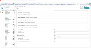
    "The application is responding and the program is loading/flashing without any problems. The exact problem I'm facing now is that,by using the "simple central" example project in CCS,  In observer configuration in BLE, whatever changes I'm making in scan type(passive and active), scan interval and scan window, I'm always getting same current consumption when measuring(about 1.95 microAmps). Why is it? also  I haven't seen anywhere what is the current consumption of CC2652R7 LP in scanning mode(passive and active). "

    Thanks.

    Best regards,

  • Hi,

    To ensure you are getting accurate power numbers, I would recommend referencing the power measurement process detailed in the Measuring CC13xx and CC26xx Current Consumption application report. A few changes should be made to the software and the device. All UART should be disabled. Any unneeded periodic events should be disabled. If using a LaunchPad, then the LED jumpers should be removed and the debugger jumpers should be removed as well.

    The datasheet contains the power draw for RX events, but this provides the current spike observed the event occurs and not the average power draw during scanning. I would recommend taking a current measurement graph and verifying if you can observe the RX and TX events in the graph as this will help confirm if you are observing the expected events.

    Best Regards,

    Jan

  • Hi Jan,

    Thank you for your time.

    "I'm trying to put the device in Observer mode and enable active and passive scan. I tried using the MultiRole project example in Code Composer Studio but it is not building the project when the device role(in sysconfig,ble) is set to observer. I'm unable to flash the device with multirole example in observer mode, while building the project this way I'm getting errors and the build is failing. please consider this query and give me a solution to put the device in observer mode to enable scan."

    Thanks.

    Best regards,

  • Hi,

    When changing roles in multi_role, there will be some code segments that must be modified for the example to compile as expected. Can the customer share the errors they are seeing? If you simply want to place the device into observer mode, then it may be better to start with the simple_central example and configure the project to use the observer mode and not form connections.

    Best Regards,

    Jan

  • Hi Jan,

    Thank you.

    "How can I put cc2652R7 in LE SCAN mode, there is no peripheral and don't want any connection event to happen, more like an observer, 
    How can I put the device in that LE SCAN mode?
    I've tried using a simple central example in CCS but in its sysconfic, in the central configuration, there is connection time, connection interval etc, I'm looking for a mode where the device doesn't expect any connection but just LE SCAN.
    please help me put the device in such a mode"

    Thanks.

    Best regards,

  • Hi,

    The simple_central example can be modified to implement an observer only functionality with few modifications. As mentioned by Kel, the SimpleLink Academy would be a very useful resources here. The SimpleLink Academy labs are a great training resource to learn about BLE, the device, and how to work with the SDK.

    Best Regards,

    Jan

  • Hi Jan,

    Thank you for your help.

    "From what I understood from the last reply I've tried the Simple Central example and have measured and plotted current using my script.
    I've set all the values as exactly as what was suggested in the response , in simple link academy resources scanning task 1(dev.ti.com/.../ble_scan_adv_basic.html), still I'm unable to get a plot which looks like the device is in scanning mode with 150ms scan interval and 150ms scan window.

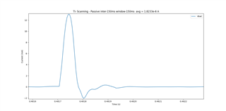
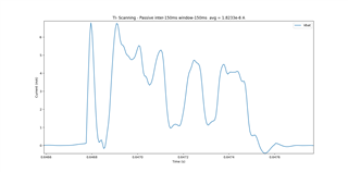
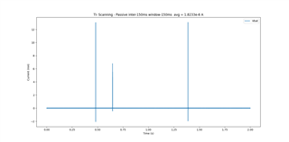
    I will attach the plot I've obtained. In the plot, I'm only seeing one scan activity spike and 2 other spikes which I believe are capacitor charging activities. But according to the parameters we've set in the simple center example, we should get a scanning activity every 150ms. but we are not getting any activities like that as you can see from the plot.
    In an entire 5 second measurement duration plot, I was able to see only 2 scan activities.

    This is the issue I'm talking about. How to put the device in scanning mode properly using simple central example.
                       
    "

    Thanks.

    Best regards,

  • Hi,

    Can you share how those plots are being generated? Is a power analyzer being used here or some other instrument?

    Best Regards,

    Jan

  • Hi Jan,

    I just received feedback from the customer.

    As I've mentioned in the previous response, That plot is obtained by using a source measurement unit and  running it using a python script of my own."
    This is the resultant graph and average current consumption that I'm observing when the device is in simple central example and in passive scan mode(as you can observe from the pictures attached to the last response from my side) and I think I'm not getting the correct values or plot."

    Thanks.

    Best regards,

  • Hi,

    Got it. My apologies if this was mentioned before, but I was unable to find it. Is the customer using a launchpad or a custom board? If they are using a LaunchPad, then could they try performing some current measurements using the EnergyTrace functionality available in the launchpad?

    Best Regards,

    Jan

  • Jan,
    I'm aware of EnergyTrace functionality and have done trying it for different modes and I've got very close/same current measurements using EnergyTrace and my script. But in this simple central example(device in scanning mode) only I'm getting this kind of an measurement result as what you have seen in the images I've attached to a previous response. I'm not getting scan signals in that scan window and scan interval I've setted for.
    What I'm again asking is  How to put the device in scanning mode with custom scan intervals and scan windows.  
    Thanks and regards,
  • Hi,

    To clarify, the device is able to scan and obtain scan reports correct?

    Best Regards,

    Jan