This thread has been locked.

If you have a related question, please click the "Ask a related question" button in the top right corner. The newly created question will be automatically linked to this question.

CC1352P: I2C Slave Device and Register Access

Part Number: CC1352P
Other Parts Discussed in Thread: SYSCONFIG

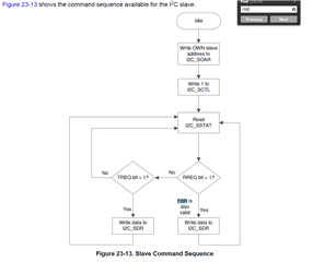
Hi. I'm trying to implement an I2C slave device using CC1352P1. I would like to activate slave mode on this device.

I've been experimenting with i2ctmp_CC1352P1_LAUNCHXL_nortos_ticlang example code.

I'm having trouble accessing/changing registers.

I've come across these threads related to my implementation so far:

https://e2e.ti.com/support/wireless-connectivity/sub-1-ghz-group/sub-1-ghz/f/sub-1-ghz-forum/789735/ccs-cc1350-cc1350/2921199?tisearch=e2e-sitesearch&keymatch=enable%20sctl#2921199

https://e2e.ti.com/support/wireless-connectivity/bluetooth-group/bluetooth/f/bluetooth-forum/1088655/cc2652rb-how-to-realize-i2c-slave-from-empty-example/4030473?tisearch=e2e-sitesearch&keymatch=I2CSlaveIntClear#4030473

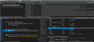
I'm trying to use interrupts to control data flow on the I2C bus. However, I can't seem to modify and see some register values. Here's a screenshot from the debug mode / registers:

I can't change or see what SCTL DA bit is. Datasheet specifies that this bit enables the I2C slave operation when set to 1.

Device specifications:

  • SCL is on pin 16 and SDA is on pin 17.
  • SCL and SDA lines are connected to the master's pins. These pins are pulled up to the master's 3V3 pin using ~6K ohm loads.
  • Slave and master devices have common grounds.
  • Master device can communicate with another device (STM32 to STM32 with interrupts). So I know master device sends requests to the address 0x3E.

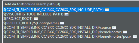
Include Options of the project:

I would like to know:

  1.  How to modify the SCTL register value.
  2.  What MTPR alters. Does that affect slave operation? I cannot modify this register value.
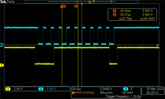
  3.  I keep seeing some garbage values when I activate master device on SDR register such as "9F", "3F", "FC" etc. periodically. Why is this not 0x05 or 101(0) instead? (refer to my code)

/*
 *  ======== main_nortos.c ========
 */
#include <stdint.h>
#include <stddef.h>

#include <NoRTOS.h>
#include <ti/drivers/Board.h>
#include <unistd.h>

/* Driver Header files */
#include <ti/drivers/GPIO.h>

/* Driver configuration */
#include "ti_drivers_config.h"
/*  User includes   */
#include "i2c_protocol.h"
#include "i2c_registers.h"
#include "D:/ccs/simplelink_cc13xx_cc26xx_sdk_6_41_00_17/source/ti/devices/cc13x2_cc26x2/driverlib/prcm.h"
extern uint8_t aTxBuffer[];
#define TASKSTACKSIZE 640

/*User function prototypes*/
void I2C_Slave_Command(void);
void Init_I2C_Slave(void);
/*
 *  ======== mainThread ========
 */
int mainThread(void )
{
    /* Call driver init functions */
    GPIO_init();
//    HWREG(GPIO_BASE + 0x48)    |= (1 << 0) | (1 << 8); // GPIO initialization example (it works!)

    /* Configure the LED and if applicable, the TMP_EN pin */
    GPIO_setConfig(CONFIG_GPIO_LED_0, GPIO_CFG_OUT_STD | GPIO_CFG_OUT_LOW);

    /*TRYING new implementation*/
    return 0;
}
/*
 *  ======== main ========
 */
I2C_Params i2cParams;
I2C_Handle i2cHandle; // Declare handle for I2C module

int main(void)
{
    Board_init();

    /* Start NoRTOS */
    NoRTOS_start();
    Init_I2C_Slave();
    /* Call mainThread function */
    mainThread();
    while (1) {

        // Run continuously
    }
}

void i2c_callback(void)
{
    uint32_t status = I2CSlaveIntStatus(I2C0_BASE, true);
    I2CSlaveIntClear(I2C0_BASE, status);

    if(status & I2C_SLAVE_INT_DATA)
    {

        while( I2CSlaveStatus(I2C0_BASE) & I2C_SLAVE_ACT_TREQ)
        {
            I2CSlaveDataPut(I2C0_BASE, 0x05); // send stuff
            GPIO_toggle(CONFIG_GPIO_LED_0);
        }
    }
}

void Init_I2C_Slave()
{
    // Initialize I2C module
    i2cHandle = I2C_open(0, &i2cParams);
    // i2c_open defaults to master mode?
    I2CMasterDisable(I2C0_BASE); // discard master settings

    // Enable Slave operation
    I2CSlaveEnable(I2C0_BASE);
    I2CSlaveIntEnable(I2C0_BASE, I2C_SLAVE_INT_START | I2C_SLAVE_INT_STOP | I2C_SLAVE_INT_DATA);

    I2CIntRegister(I2C0_BASE, i2c_callback);

    // Enable Serial Power Domain
    PRCMPeripheralRunEnable(PRCM_PERIPH_I2C0);
    PRCMPeripheralSleepEnable(PRCM_PERIPH_I2C0);

    HWREG(PRCM_BASE + I2CCLKGR)     |= (1 << 0) | (1 << 8); // clk config

    // Mandatory Load PRCM settings
    HWREG(PRCM_BASE + CLKLOADCTL)   |= (1 << 0);
    // Configure IOC module to use I2C pins
    IOCPinTypeI2c(I2C0_BASE, Board_I2C_SDA, Board_I2C_SCL);


    // Write the slave address
    HWREG(I2C0_BASE + I2C_SOAR)    = 0x3E; // 0x3E

}

Could you help me please?

  • Hi Yusuf,

    First, I would advise against mixing I2C driver calls (I2C_open) and I2C driverlib ones, as the I2C driver will indeed configure many things that might go against your goal of having an I2C slave.

    For your first question, you can modify SCTL as you have described, but be aware that the register is write only (see Chapter 23.5.1.3 of the Technical Reference Manual). If you want to check that the value has been indeed written, you have the read the SSTAT register.

    Second question, MTPR only affects the master device.

    As of the third question, have you done a logic capture, and can you share what does the data looks like on the I2C bus?

    Also, it would be maybe better to use I2CSlaveAddressSet() or I2CSlaveInit() in order to set the slave address: https://dev.ti.com/tirex/explore/content/simplelink_cc13xx_cc26xx_sdk_7_10_00_98/docs/driverlib_cc13xx_cc26xx/cc13x2_cc26x2/driverlib/group__i2c__api.html#ga61e5ac82b6481401c1b38c7cf0d96ed9

    Regards,

    Arthur

  • I see, thanks for the heads up. However, SSTAT register remains 0 even when I write to SCTL. Note that this is Nortos so I'm planning on trying it on TI-RTOS-7 with the pin configuration libraries to make sure that my initialization of I2C pins are correct. I'll share the oscilloscope snapshots if I can't solve the problem.

  • Master expects a buffer with the size of 5.

    I've tried this by editing both master and slave devices:

    /* Buffer used for transmission */
    uint8_t aTxBuffer[] = "[MSG]";
    uint8_t bufSize = 5;
    
    void i2c_callback(void)
    {
        uint32_t status = I2CSlaveIntStatus(I2C0_BASE, true);
        I2CSlaveIntClear(I2C0_BASE, status);
    
        if(status & I2C_SLAVE_INT_DATA)
        {
    
            while( I2CSlaveStatus(I2C0_BASE) & I2C_SLAVE_ACT_TREQ)
            {
                for(int i  = bufSize; i>0; i--)
                {
                    I2CSlaveDataPut(I2C0_BASE, aTxBuffer[i]); // send stuff
                }
                GPIO_toggle(CONFIG_GPIO_LED_0);
            }
        }
    }

    Here is the oscilloscope view of SCL/SDA lines (SCL: Blue):

    Is there a way to send the data buffer at once? I'm not sure whether that's the problem. The master device expects a certain buffer size.. The exact size of "[MSG]" string buf.

    Sometimes in the debug mode, when I pause and unpause the launchpad a couple of times, I see TREQ bit 1 but that's it. SDR keeps changing between 3F, FC, F3 etc..

  • I observe that master is not receiving any interrupt.

  • Hi Yusuf,

    Can you confirm that the master device is the STM32?

    Regards,

    Arthur

  • Yes. I've tested this setup with the STM32 slave device too. It has the slave address defined as 0x3E. It receives interrupts continuously using HAL_I2C_Master_Receive_IT.

  • /*
     *  ======== empty.c ========
     */
    
    /* For usleep() */
    #include <unistd.h>
    #include <stdint.h>
    #include <stddef.h>
    
    /* Driver Header files */
    #include <ti/drivers/GPIO.h>
    #include <ti/drivers/I2C.h>
    // #include <ti/drivers/SPI.h>
    // #include <ti/drivers/Watchdog.h>
    
    /* Driver configuration */
    #include "ti_drivers_config.h"
    
    #include "D:/ccs/simplelink_cc13xx_cc26xx_sdk_6_41_00_17/source/ti/devices/cc13x2_cc26x2/driverlib/prcm.h"
    #include <ti/drivers/Power.h>
    #include <ti/drivers/power/PowerCC26XX.h>
    #include <ti/devices/DeviceFamily.h>
    #include DeviceFamily_constructPath(driverlib/i2c.h)
    #include DeviceFamily_constructPath(driverlib/ioc.h)
    #include DeviceFamily_constructPath(inc/hw_memmap.h)
    
    #define I2C0_SCL0         IOID_16
    #define I2C0_SDA0         IOID_17
    #define SLAVE_ADDR        0x3E
    #define I2C_SSTAT         0x004
    #define CONTROL_MASK_FBR  0b100
    #define CONTROL_MASK_TREQ 0b010
    #define CONTROL_MASK_RREQ 0b001
    void init_i2c(void);
    void i2c_callback(void);
    
    /* Buffer used for transmission */
    uint8_t aTxBuffer[] = "[MSG]";
    uint8_t bufSize = 5;
    /*
     *  ======== mainThread ========
     */
    void *mainThread(void *arg0)
    {
        /* Configure the LED pin */
        GPIO_init();
        GPIO_setConfig(CONFIG_GPIO_LED_1, GPIO_CFG_OUT_STD | GPIO_CFG_OUT_LOW);
        GPIO_setConfig(CONFIG_GPIO_LED_0, GPIO_CFG_OUT_STD | GPIO_CFG_OUT_LOW);
        GPIO_write(CONFIG_GPIO_LED_1, CONFIG_GPIO_LED_ON);
        init_i2c();
    
        uint32_t transmission_status;
    
        transmission_status = HWREG(I2S0_BASE + I2C_SSTAT); // read the status
    
    
        while (1)
        {
    
            GPIO_toggle(CONFIG_GPIO_LED_1);
    
            // Compare status bits 2, 1 and 0.
            if((transmission_status & CONTROL_MASK_FBR) != 0)
            {
            // Do nothing
            }
    
            if((transmission_status & CONTROL_MASK_TREQ) != 0)
            {
                GPIO_toggle(CONFIG_GPIO_LED_0);
            }
    
            if((transmission_status & CONTROL_MASK_RREQ) != 0)
            {
                GPIO_toggle(CONFIG_GPIO_LED_1);
            }
        }
        return 0;
    }
    
    void i2c_callback(void)
    {
        uint32_t status = I2CSlaveIntStatus(I2C0_BASE, true);
        I2CSlaveIntClear(I2C0_BASE, status);
    
        if(status & I2C_SLAVE_INT_DATA)
        {
    
            while( I2CSlaveStatus(I2C0_BASE) & I2C_SLAVE_ACT_TREQ)
            {
                for(int i  = 0; i< bufSize; i++)
                {
                    I2CSlaveDataPut(I2C0_BASE, aTxBuffer[i]); // send stuff
                }
                GPIO_toggle(CONFIG_GPIO_LED_0);
            }
        }
    }
    
    void init_i2c(void)
    {
        PRCMPowerDomainOn(PRCM_DOMAIN_PERIPH);
    
        // Set Power dependecies & constraints
        Power_setDependency(PowerCC26XX_PERIPH_I2C0);
        Power_setDependency(PowerCC26XX_PERIPH_GPIO);
    
        // Set constraints for Standby, powerdown and idle mode
        Power_setConstraint(PowerCC26XX_SB_DISALLOW);
        Power_setConstraint(PowerCC26XX_IDLE_PD_DISALLOW);
    
        PRCMLoadSet();
        PRCMPeripheralRunEnable(PRCM_PERIPH_I2C0); // Enable I2C module
        PRCMPeripheralRunEnable(PRCM_PERIPH_GPIO);
        PRCMLoadSet();
    
        // IOC configuration for I2C pins
        IOCPortConfigureSet(I2C0_SCL0, IOC_PORT_MCU_I2C_MSSCL,IOC_STD_INPUT);
        IOCPortConfigureSet(I2C0_SDA0, IOC_PORT_MCU_I2C_MSSDA,IOC_STD_INPUT);
    
    
        I2CSlaveInit(I2C0_BASE, SLAVE_ADDR);
        I2CIntRegister(I2C0_BASE, i2c_callback);
        I2CSlaveIntEnable(I2C0_BASE, I2C_SLAVE_INT_START | I2C_SLAVE_INT_STOP | I2C_SLAVE_INT_DATA);
    }
    

    ^^^ This is the code that I'm running overall on TI RTOS7. 

    When I try to initialize IOC pins of I2C with open drain using:  

        PIN_Config i2cPinTable[] = {
            I2C0_SDA0 | PIN_INPUT_EN | PIN_PULLUP | PIN_OPENDRAIN,
            I2C0_SCL0 | PIN_INPUT_EN | PIN_PULLUP | PIN_OPENDRAIN,
            PIN_TERMINATE
        };

    I can't use pin config functions. I can't include the previously mentioned path on include options ${COM_TI_SIMPLELINK_CC13X2_26X2_SDK_INSTALL_DIR}/source/ti/devices/cc13x2_cc26x2/driverlib

    I've tried using the pin configurations predefined as IOC_IOMODE_OPEN_DRAIN_NORMAL but that didn't work at all. Still no change on TREQ bit. Open drain mode causes SDR to become completely zero.

  • Hi Yusuf,

    Just a quick note, I see that the path is COM_TI_SIMPLELINK_CC13X2_26X2_SDK_INSTALL_DIR.

    That means you have an older SDK. Newer SDKs do not have the PIN driver, and instead use the GPIO driver.

    What SDK version are you using?

    Regards,

    Arthur

  • Hi Arthur,

    So that's why I can't find the function in included drivers. My SDK package is

    SimpleLink CC13xx CC26xx SDK 7.10.00.98

    Is open drain configuration necessary to make this slave device work? Any suggestions?

  • I've realized that I'm getting an error when I pause in debug mode:

  • Hi Yusuf,

    I see a bug that might cause that. At line 54 of the code you posted:

    transmission_status = HWREG(I2S0_BASE + I2C_SSTAT); // read the status

    It should probably be

    transmission_status = HWREG(I2C0_BASE + I2C_SSTAT); // read the status

    If you step by step through your code (F5 is CCS) with your current code, it is very likely that it won't go past that line without the fix.

    Regards,

    Arthur

  • Ohh I see now okay sorry about that.

  • Still no interrupts received on master end.

  • Update: I've managed to send some data over the SDA line. I've set configurations to make sure that Pull up is disabled (input mode).

    • In .syscnfg file for both SCL and SDA pins; Pull is set none
    • I've defined input configuration as:


    #define IOC_USER_INPUT          (IOC_CURRENT_2MA | IOC_STRENGTH_AUTO |      \
                                IOC_NO_IOPULL | IOC_SLEW_DISABLE |              \
                                IOC_HYST_DISABLE | IOC_FALLING_EDGE |           \
                                IOC_INT_ENABLE | IOC_IOMODE_OPEN_DRAIN_NORMAL | \
                                IOC_NO_WAKE_UP | IOC_INPUT_ENABLE )
                                
    //*Initialized pins using: *//
        IOCPortConfigureSet(I2C0_SCL0, IOC_PORT_MCU_I2C_MSSCL,IOC_USER_INPUT );
        IOCPortConfigureSet(I2C0_SDA0, IOC_PORT_MCU_I2C_MSSDA,IOC_USER_INPUT );

    Now I'm trying to see what causes this slave to send data only for once as I turn master device off.

    For instance, when I'm putting data 0x0B over the SDA line, when both master and slave devices are on, I see 0x3F constantly.

    As I turn master off and keep slave (CC1352) on, I see 0x17 which means it sent B as desired. And it repeats as I toggle the master's power line. This only happens when I have another slave connected to the SDA SCL pins that is constantly sending data.

    I've tried removing STM32 slave device and the CC1352 does not receive any transmit requests since TREQ is always 0 and I see 3F, 9F, E7, FC etc.. on SDR in debug mode.

  • Hi Yusuf,

    Is it possible that the master device is somehow pulling the I2C lines incorrectly?

    Can you communicate between a CC1352 slave and and CC1352 master device?

    Regards,

    Arthur

  • Hi Arthur,

    I've tired that and there was no connection between two CC1352 devices. In debug mode, master device gives arbitration loss error.

    Master code:

    //* I2C Pins *//
    #define I2C0_SCL0         IOID_16
    #define I2C0_SDA0         IOID_17
    
    
    /*
     *  ======== mainThread ========
     */
    void *mainThread(void *arg0)
    {
    
        /* Call driver init functions */
        GPIO_init();
        Init_m_i2c();
        // data buffer
        uint8_t bufSize = 4;
        char dataReceived[bufSize];
    
        for(;;)
        {
            master_I2C_read(SLAVE_ADDR, bufSize, dataReceived);
        }
    
    
        return(0);
    }
    
    void Init_m_i2c()
    {
        /*Power domain*/
        PRCMPowerDomainOn(PRCM_DOMAIN_PERIPH);
    
        // Set Power dependecies & constraints
        Power_setDependency(PowerCC26XX_PERIPH_I2C0);
        Power_setDependency(PowerCC26XX_PERIPH_GPIO);
    
        // Set constraints for Standby, powerdown and idle mode
        Power_setConstraint(PowerCC26XX_SB_DISALLOW);
        Power_setConstraint(PowerCC26XX_IDLE_PD_DISALLOW);
    
        PRCMLoadSet();
        PRCMPeripheralRunEnable(PRCM_PERIPH_I2C0); // Enable I2C module
        PRCMPeripheralRunEnable(PRCM_PERIPH_GPIO);
        PRCMLoadSet();
    
        /* LED Configuration */
        GPIO_setConfig(CONFIG_GPIO_LED_0, GPIO_CFG_OUT_STD | GPIO_CFG_OUT_LOW);
        GPIO_setConfig(CONFIG_GPIO_LED_1, GPIO_CFG_OUT_STD | GPIO_CFG_OUT_LOW);
        GPIO_write(CONFIG_GPIO_LED_0, CONFIG_GPIO_LED_ON);
        GPIO_write(CONFIG_GPIO_LED_1, CONFIG_GPIO_LED_ON);
    
        /*Master I2C0 Configuration*/
        IOCPortConfigureSet(I2C0_SCL0, IOC_PORT_MCU_I2C_MSSCL,IOC_STD_INPUT );
        IOCPortConfigureSet(I2C0_SDA0, IOC_PORT_MCU_I2C_MSSDA,IOC_STD_INPUT );
    
        I2CMasterEnable(I2C0_BASE);
        I2CMasterIntEnable(I2C0_BASE);


    }
    
    void master_I2C_read(uint8_t slaveAddress, uint8_t length, char * rxData)
    {
    
        I2CMasterSlaveAddrSet(I2C0_BASE, slaveAddress, true); //true to read, false to write
        I2CMasterControl(I2C0_BASE, I2C_MASTER_CMD_SINGLE_RECEIVE);
    
        while(I2CMasterBusy(I2C0_BASE))
        {
            // wait till available
        }
    
        for(int i = 0; i < length; i++)
        {
            rxData[i] = I2CMasterDataGet(I2C0_BASE);
        }
        // end of reception
    }
    
    void master_I2C_write(uint8_t slaveAddress, uint8_t length, char * txData)
    {
    
        I2CMasterSlaveAddrSet(I2C0_BASE, slaveAddress, true);
    
        I2CMasterControl(I2C0_BASE, I2C_MASTER_CMD_SINGLE_SEND);
    
        while(I2CMasterBusy(I2C0_BASE))
        {
            // wait till available
        }
    
        for(int i = 0; i < length; i++)
        {
            txData[i] = I2CMasterDataGet(I2C0_BASE);
        }
    }

    I'm not sure if my configurations are correct here. I've followed the datasheet I2C communication flow chart.

    This master device won't respond to any devices.

  • Hi yusuf,

    I think it would be easier, at least to rule out a configuration error, to use the I2C Driver (the one used in the i2ctmp example), for the master, at least for now.

    That way we can rule out any problem with clock/pin configuration.

    In this example you provided, you could just replace Init_m_i2c(), and master_I2C_read by I2C_init(), I2C_open, and I2C_transfer, as seen in that example (after having added the instance in sysconfig):

    // Import I2C Driver definitions
    #include <ti/drivers/I2C.h>
    
    // Define name for an index of an I2C bus
    #define SENSORS 0
    
    // Define the target address of device on the SENSORS bus
    #define OPT_ADDR 0x47
    
    // One-time init of I2C driver
    I2C_init();
    // initialize optional I2C bus parameters
    I2C_Params params;
    I2C_Params_init(&params);
    params.bitRate = I2C_400kHz;
    
    // Open I2C bus for usage
    I2C_Handle i2cHandle = I2C_open(SENSORS, &params);
    
    // Initialize target address of transaction
    I2C_Transaction transaction = {0};
    transaction.targetAddress = SLAVE_ADDR;
    
    // Read from I2C target device
    transaction.readBuf = data;
    transaction.readCount = sizeof(data);
    transaction.writeCount = 0;
    I2C_transfer(i2cHandle, &transaction);
    
    // Close I2C
    I2C_close(i2cHandle);

    (from https://dev.ti.com/tirex/explore/content/simplelink_cc13xx_cc26xx_sdk_7_10_00_98/docs/drivers/doxygen/html/_i2_c_8h.html)

    Regards,

    Arthur

  • Hi Arthur, I've made sure that my CC1352 device works in master mode.I've enabled pull up pins on both SCL and SDA and a temperature sensor works as expected. (I'm using an external temp. sensor)

    /*
     *  ======== i2ctmp.c ========
     */
    #include <stdint.h>
    #include <stddef.h>
    #include <unistd.h>
    
    /* Driver Header files */
    #include <ti/drivers/GPIO.h>
    #include <ti/drivers/I2C.h>
    
    /* Driver configuration */
    #include "ti_drivers_config.h"
    
    /*user includes*/
    #include "D:/ccs/simplelink_cc13xx_cc26xx_sdk_6_41_00_17/source/ti/devices/cc13x2_cc26x2/driverlib/prcm.h"
    #include <ti/drivers/power/PowerCC26XX.h>
    
    #define TASKSTACKSIZE 640
    
    /* I2C target addresses */
    #define SLAVE_ADDR    0x3E
    
    #define SENSORS 0    // sensor index


    /*
     *  ======== mainThread ========
     */
    float temperature;
    void *mainThread(void *arg0)
    {
        /*I2C Variable Declerations*/
        static I2C_Handle i2c;
        static I2C_Params i2cParams;
        static I2C_Transaction i2cTransaction;
    
        static uint8_t i2cRxBuffer[2];
        static uint8_t i2cTxBuffer[1];
        static uint8_t i2cTempSensorAddress = 0x40;
        static uint8_t i2cTempSensorTempRegister = 0xE3;
    
    
        /*I2C Initialization*/
        I2C_init();
        /* Create I2C for usage */
        I2C_Params_init(&i2cParams);
        i2cParams.bitRate = I2C_100kHz;
        i2c = I2C_open(CONFIG_I2C_TMP, &i2cParams);
        /* Common I2C transaction setup */
        i2cTransaction.writeBuf      = i2cTxBuffer;
        i2cTransaction.writeCount    = 1;
        i2cTransaction.readBuf       = i2cRxBuffer;
        i2cTransaction.readCount     = 0;
        i2cTransaction.targetAddress = i2cTempSensorAddress;
        i2cTransaction.readCount     = 2;
        i2cTxBuffer[0]               = i2cTempSensorTempRegister;
    
        for(;;)
        {
    
            if (I2C_transfer(i2c, &i2cTransaction)){
                uint16_t temperatureRaw = (i2cRxBuffer[0] << 8) | i2cRxBuffer[1];
                temperature = ((float)temperatureRaw *0.00268127441f) - 46.85f;
            }
            for(int i = 0; i<= 1000000; i++){
    //            for(int i = 0; i<= 1000000; i++)
            }
        }
    
    
        return(0);
    }
    

     Now, how can I make a simple slave implementation on this device? I would like to use this slave CC1352 to send some data as a master makes a transmit request.

  • Hi Arthur. Thank you for your assistance.

    I've figured out how to send and receive data as a slave CC1352P1 device. Fortunately, the problem was on the master device (STM32) side.

    STM32 requires write/read bits specified which is not done automatically by its library functions.

    Ex: Slave address is set as 0x3E, master shall

    A) target 0x7D to make slave transmit requests.

    B) target 0x7C to make slave receive requests. (I thought HAL functions handled write and read bits automatically...)

    Here's what I've implemented to transfer 11 bytes from slave to master:

    /*slave mode I2C*/
    /*
     *  ======== i2ctmp.c ========
     */
    #include <stdint.h>
    #include <stddef.h>
    #include <unistd.h>
    
    /* Driver Header files */
    #include <ti/drivers/GPIO.h>
    #include <ti/drivers/I2C.h>
    
    /* Driver configuration */
    #include "ti_drivers_config.h"
    
    #define TASKSTACKSIZE 640
    #include <string.h>
    
    #include <ti/drivers/Power.h>
    #include <ti/drivers/power/PowerCC26XX.h>
    #include "D:/ccs/simplelink_cc13xx_cc26xx_sdk_6_41_00_17/source/ti/devices/cc13x2_cc26x2/driverlib/prcm.h"
    #include <ti/devices/DeviceFamily.h>
    #include DeviceFamily_constructPath(driverlib/i2c.h)
    #include DeviceFamily_constructPath(driverlib/ioc.h)
    #include DeviceFamily_constructPath(inc/hw_memmap.h)
    
    #define Board_I2C_SCL0   14
    #define Board_I2C_SDA0   13
    
    #define I2C_SLAVE_ADDR   0x3E
    
    void i2c_callback(void);
    int counter;
    char i2cData[11] = "4CHARS_SENT";
    uint32_t status = 0;
    
    
    void *mainThread(void *arg0)
    {
        Power_setDependency(PowerCC26XX_PERIPH_I2C0);
        IOCPinTypeI2c(I2C0_BASE, Board_I2C_SDA0, Board_I2C_SCL0);
        I2CSlaveInit(I2C0_BASE, I2C_SLAVE_ADDR);
    
        I2CSlaveIntEnable(I2C0_BASE, I2C_SLAVE_INT_START | I2C_SLAVE_INT_STOP | I2C_SLAVE_INT_DATA);
        I2CIntRegister(I2C0_BASE, i2c_callback);
        while (1)
        {
            size_t index = 0;
            for (index = 0; index < 11; index++)
            {
                while (I2CSlaveStatus(I2C0_BASE) != I2C_SLAVE_ACT_TREQ);
                I2CSlaveDataPut(I2C0_BASE, i2cData[index]);
            }
            GPIO_toggle(CONFIG_GPIO_LED_0);
        }
    
        return NULL;
    }
    void i2c_callback(void)
    {
        uint32_t status = I2CSlaveIntStatus(I2C0_BASE, true);
        I2CSlaveIntClear(I2C0_BASE, status);
        counter++;
    }

    This solves my issue, but there's a minor issue that FBR, TREQ or RREQ don't ever change during these transmissions.

    Even though I constantly receive "4CHARS_SENT" on the master periodically, these bits don't change.

    SDR register value is frozen too (stuck at AA for some reason).

    I've tried putting breakpoints, led toggles to see if I2CSlaveStatus(I2C0_BASE) == I2C_SLAVE_ACT_TREQ) etc and, none were triggered at all. It seems these bits are not affected. Is this a bug?

    I've confirmed that I don't have any errors on the master end regarding I2C transmissions.

  • Hi Yusuf,

    Glad you have figured it out, and thanks for the example. This will be very useful for other customers as well.

    About your RREQ issue, it seems like that bit is getting cleared automatically AFTER you have read data from the SDR register. It does not look like you have to clear the interrupt yourself for that case.

    Regards,

    Arthur