


Part Number: CC2652P
We are struggling with an existing design based on CC2652P1FRGZR. We have an evaluation board that works fine, while the attached schematic diagram provides very poor coverage (i.e., the maximum distance where the signal can be detected and a connection can be established is just a couple of meters).
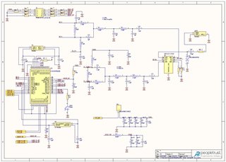
Our first guess was that the RF switch S2 was not correctly set. However, we checked all possible configurations of it, and it seems that it's not the root cause of the problem.
We noticed that the matching networks used (L2, L5, L6, C41, C45, etc.) have quite different values with respect to the values we find on the evaluation board or on other schematic diagrams. The person who designed this schematic diagram a couple of years ago does not remember which reference design he used. So, we wonder if the matching network of the attached schematic diagram is correct. If the tuning of the network is completely wrong, this would definitely justify the problems that we are experiencing.
Can anyone help?
