This thread has been locked.

If you have a related question, please click the "Ask a related question" button in the top right corner. The newly created question will be automatically linked to this question.

CC2640R2F: Co-processor issue

Part Number: CC2640R2F

Hi Team,

Requirement: The coprocessor takes data through SPI every 1ms and sends it to the host processor. 

1) 

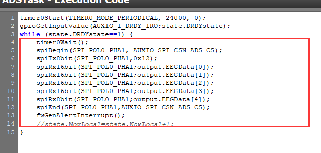
A. If initializing with the following code, using CCS debugging, it can be seen that an SPI request is initiated every 1ms. AUXIO_I_DRDY_IRQ is always high, so the dead loop always runs, fwGenAlertInterrupt wakes up and the main processor scTaskAlertCallback does not execute.


B. The customer wakes up the system to move it as shown in the following code. Toggle level every time scTaskAlertCallback is executed, use the 1-pin test of the logic analyzer, theoretically it should not flip. but the logic analyzer was only executed once.  Why's this?

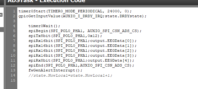
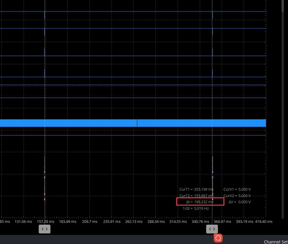
C. By removing the dead loop into the following code, it can be seen from the logical analysis that the data is not taken every 1 ms. Why?

D. The above data is captured by the logic analyzer in the CCS development tool debug mode, when the code is ported and the coprocessor and M3 work together, compare the figure of the above question C, you can see that the SPI signal cannot be captured, but the signal toggles when scTaskAlertCallback is acquired. The figure above(Question C) captures the SPI signal, but cannot capture the signal that toggles when scTaskAlertCallback is active. The signals that can be captured during debug and runtime of the CCS development tool are the opposite. It is hard to determine exactly what the SPI signal looks like when the system is running properly after the code is ported. 

2) Based on the above picture of the logic analyzer, it can be basically determined that scTaskAlertCallback is executing. Takes the SPI data out and sends it to the host, but strange that the host receives exactly the same data. 

3) Based on the green data for question 2, the difference is because the customer manually changed the first data at the time of the test. Code D2 should be followed by D3, and this becomes D4 on the host. And the problem is common, and there is even a case where E8 is followed by 44. Why's this?

Could you please help check this case? Thanks.

Best Regards,

Cherry

  • Hi Cherry,

    Just for clarity coprocessor is sensor controller.

    Your customer issue is cannot read the EEG using sensor controller SPI interface. I would advice your customer to not use sensor controller but instead use the TI RTOS SPI driver.

    Once your customer have made the SPI communication work using TI RTOS SPI drivers then try sensor controller method. After that find out what is the benefit of using sensor controller for this application. If there is none don't use the sensor controller.

    -kel

  • Hi Cherry,

    It appears that you are continuing the work from Alex: https://e2e.ti.com/f/1/t/1262851 

    Please have the customer start with default SCS examples and fully understand this operation before attempting to implement their custom application.  By developing their code in incremental steps, they may be able to avoid having multiple issues at once and then the E2E forum can help address singular problems as they arise.

    Regards,
    Ryan

  • Hi Markel and Ryan,

    Thank you for the support.

    Please let me clarify more on this case:

    The customer has made SPI communication work using TI RTOS SPI driver to get EEG data captured by the analogue front end.

    The reason why they would like to use the coprocessor is they want to do low-power development, collecting data through the coprocessor, and waking up the M3 when some data was captured.

    Regarding the examples of SCS, which have been running successfully, indeed the above issues are found in real development. But there are fewer resources available for the development of SCS, could you help troubleshooting what should be done? 

    Thanks and regards,

    Cherry

  • Leaning on the SCS Help Documentation, the customer should use Task Debugging and Run-Time Logging to ensure that the SCS core is operating as intended.  Then it is for the main CC2640R2F core to properly manage/handle the SCIF OSAL and debug accordingly.  I recommend taking incremental steps from the working example code to establish where the issue is introduced.

    Regards,
    Ryan

  • Hi Ryan,

    1) When debugging with the debugger that ships with CCS, use the following code (state.DRDYstate is always 1) a dead loop that transfers data every 1 ms:

    However, after removing the dead loop, there is a large gap between the two transmissions.

    Only executing code is running in debug: 

    2) This should be an 8-ms wake-up, but it is actually at the us level, depending on the coprocessor Time0 usage: 

    Thanks and regards,

    Cherry

  • Hi Cherry,

    Execution code runs one time for each task iteration triggered by the RTC, or when triggered manually by the System CPU application.  The RTC tick period is configured by the System CPU application using the scifStartRtcTicksNow() / scifStartRtcTicks() function.  Please be sure to fully read through and understand both Timer 0 and RTC-Based Execution Scheduling modules from the SCS Help Documentation.

    Regards,
    Ryan