This thread has been locked.

If you have a related question, please click the "Ask a related question" button in the top right corner. The newly created question will be automatically linked to this question.

CC2652PSIP: UART0 pins for Bootloader

Part Number: CC2652PSIP
Other Parts Discussed in Thread: CC2538, SYSCONFIG, CC2652P, CC1352P

Hello,

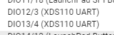
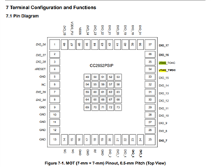
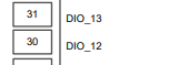
What pins of the CC2652PSIP chip are assigned for UART0 by Bootloader: DIO2,DIO3 or DIO12,DIO13 ?

The following documents "CC13x2, CC26x2 SimpleLink Wireless MCU" and "CC2538/CC26x0/CC26x2 Serial Bootloader Interface" have information only for CC26X2R.

Thanks,

Alex 

  • Hello Alex,

    I hope you are well. Looking at the Serial Bootloader Interface document on table 2-8 shows some of the pins that the bootloader will use for our devices, but as you noticed it does not clearly address which pins the CC2652PSIP uses. Looking at sysconfig, the pins seem to be DIO12/13 (the XDS pins which we can use the test the ROM bootloader with the debugger).


    The CC2652P device is pin compatible/identical to the CC1352P device, as per dev.ti.

    I hope this information is useful!

    Thanks,
    Alex F

  • Hello Alex F,

    Thanks for so fast response. The reason for my question was that I was surprised that my board with CC2652PSIP is connected to PC using micro's pins DIO12 and DIO13 and I can run all Bootloader functions using the software "SmartRF Flash Programmer 2" But surprise is here: the 2-pin cJTAG is used (not UART0) !

    Documentation says that only UART0 and SSI0 are assigned and used by Bootloader. Is cJTAG assigned to pins DIO12 and DIO13 by Bootloader as well? Is it some an undocumented new development? Does TI have any document about that?

    Thanks,

    Alex S

  • Hello Alex S,

    Looking into the datasheet, it seems like a part of the answer lies here:

    The default is the cJTAG, which is what you have noticed! 

    In terms of what two pins the cJTAG could be using it might be pins 34/35, however I will need to confirm this with the team. 

    The TRM also has more information on the cJTAG operation if you are interested CC13x2, CC26x2 SimpleLinkTm Wireless MCU Technical Reference Manual (Rev. F) (ti.com). In this case JTAG is still important for the ICEPick process. 

    Thanks,
    Alex F

  • Hello Alex F,

    I can say only that CC2652PSIP's Bootloader assigns cJTAG to the DIO12 and DIO13. The CC2652PSIP's ROM-based Bootloader can communicate with three (not two) peripherals: UART0, SSI0 and cJTAG.  

    I noted that CC2552PSIP has different package than two identical chips CC2652P and CC1352P. 

    Thanks,

    Alex S.

  • Hello Alex S,

    If you want to specifically target the ROM bootloader you will need to use the DIO12/DIO13, which are pins 30/31 on the CC2652PSIP device.

    The two cJTAG pins are JTAG_TMSC, and JTAG_TCKC, which are pins 34/35 on the CC2652PSIP device, these are used for the debugging option. 

    The pinout from a user perspective may be slightly different for the CC2652PSIP than the CC2652P. 

    The SmartRF Flash Programmer 2 can be used to program the flash memory, over both the debug and serial interfaces. You should be able to use Flash Programmer to check where the bootloader pins or cJTAG pins are active. If you for example do not have cJTAG connected, Flash Programmer will instead try to use the bootloader pins; you should be able to confirm if cJTAG is active by debugging an CCS example with your same HW configuration. 

    Thanks,
    Alex