This thread has been locked.

If you have a related question, please click the "Ask a related question" button in the top right corner. The newly created question will be automatically linked to this question.

CC2340R5: add low power mode to Basic BLE code example & Energy Trace Not work

Part Number: CC2340R5
Other Parts Discussed in Thread: ENERGYTRACE, , SYSCONFIG, CCSTUDIO

Hello Team,

I am new to TI interface and MCU family. I am developing some application using cc2340r5 MCU. Overall details are attached below.

CCS: 12.4.0.00007
Freertos TIclang
simplelink_lowpower_f3_sdk_7_40_00_64
Code Example Link

Custom build Hardware (it is working condition since I tested led blink and basic ble code)
using XDS110 Debug for programing


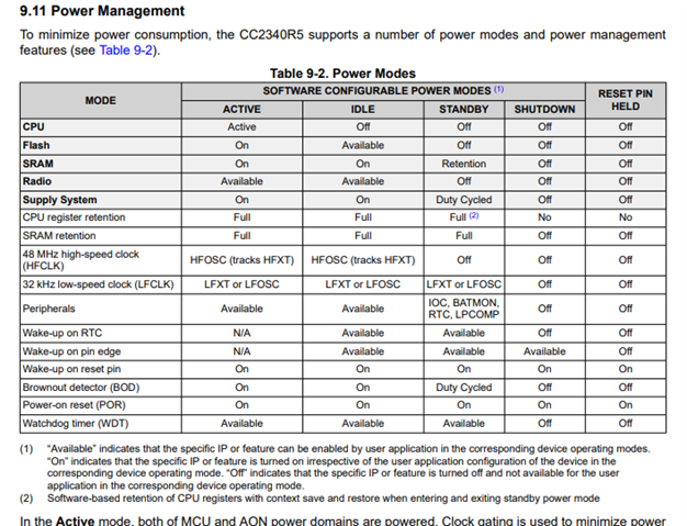
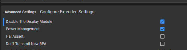
I use a Basic BLE code example and want to add a low-power mode. So basically my requirement is when MCU is not transmitting any data for connection it needs to be in as deep sleep as possible and when time comes it wakes up and sends the connection data and goes back to sleep. 

So the basic idea is BLE send beacon data and wait for the mobile app to establish the connection. If the connection is not established it will stay in low-power mode and if the connection is established it will be in active mode.

Need help to understand where and what I have to add in code to make it possible. tried to search code examples and other references but had no success. 

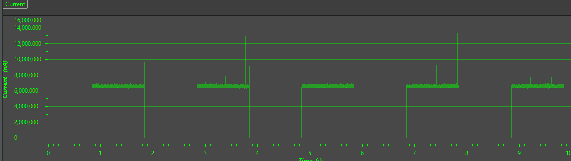
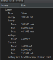
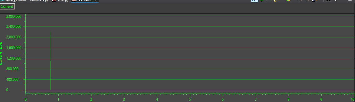
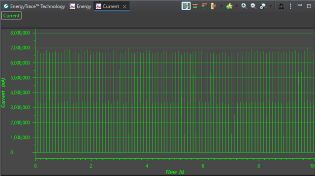
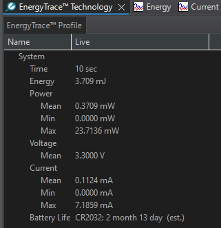
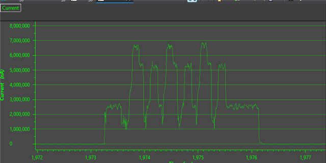
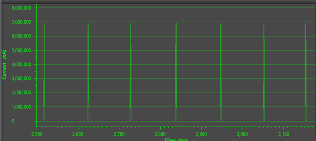
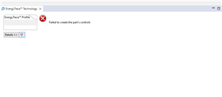
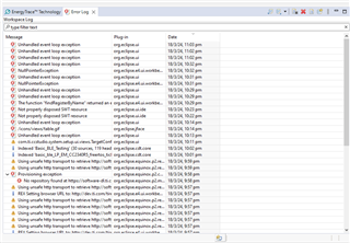
Also, I tried to run an energy trace to see the power number but it is not working.

Thanks
Bhavik

  • Hi Bhavik,

    By default, the Power Manager in the SimpleLink Low Power F3 SDK will attempt to go the lowest power mode possible. BLE will not wake the device from standby unless it must perform RF after which it will go back to standby. To put the CC2340R5 into the lowest power mode possible when using a BLE example, then the display must be disabled and the LED jumpers should be removed from the board. It is also recommended to power the board externally by applying voltage to the 3.3V pin and ground to the ground pin.

    Can you share the EnergyTrace error you are facing? It should work out of the box within CCS.

    Best Regards,

    Jan

  • Hi Jan,

    Still if i need to keep it further down to save more power is there any way to do that? If yes where and how?

    For Energy trace, it opens a small window called progress information see attached image. Once it gets complete it is not giving anything apart from that.


  • Hi Jan,

    Now i am getting error as seen in attached image.

  • Hi,

    Got it. Thank you for providing these logs. Are you using a LP-EM-CC2340R5 as your dev board? Also, how did you install the SDK? Did you install it through the TI Resource Explorer or through the .exe installer available on ti.com?

    Still if i need to keep it further down to save more power is there any way to do that? If yes where and how?

    The power manager will place the device in the lowest mode possible depending on what is running. For example, if driver is always active and preventing standby, then the power manager will not be able to achieve standby and at most will go down to idle. You cannot force the power manager to override the driver. However, you can close the driver or configure the driver to allow standby. Some additional information about this may be found in the Power, Reset, and Clocking section of the TRM. Section 9.11 Power Management of the datasheet contains a table that provides information on the lowest power setting each driver and peripheral allows while it is active:

    Best Regards,

    Jan

  • Hi,

    Installed using through TI Resource Explorer.

    how to solve the issue related to energy trace.

    Also can you suggest a best way to identify which power mode it is when code is running?

  • Hi,

    Got it. Can you try installing the SDK from the website?

    https://www.ti.com/tool/download/SIMPLELINK-LOWPOWER-F3-SDK/7.40.00.64

    Also, can you verify which CCS version you are using? CCS 12 is recommended for use with the 7.40 SDK.

    Best Regards,

    Jan

  • Hi,

    Led me try it and get back to you.

    Thanks

  • Hi,

    Also can you suggest a best way to identify which power mode it is when code is running?

    Thanks

  • Hi,

    To clarify, if the device is running application code, then it is in active mode. So if you were to check what power state the device is in within application code it should always return active. That said, you are able to use the power callbacks to determine which state the device was in pre-wakeup. The following E2E thread provides some information on this:

    https://e2e.ti.com/support/wireless-connectivity/bluetooth-group/bluetooth/f/bluetooth-forum/1255184/lp-em-cc2340r5-how-to-know-wake-up-mode-from-power-on-or-shutdown

    Best Regards,

    Jan

  • Hi Jan,

    I tried to debug using debugger to check weather it really goes into power down mode or it really comes out from that or not and i can see that it is not happening. Also, I am able to use power trace properly now but only when using debug and by looking at current and power graph also i can not see any low power activity. I really need to understadn that how it happen in Code Examples (CEs) mainly in basic BLE.

    Also, can you provide any link which just talks about switching between various power mode?

    Since I am trying to develop some simple test application to unserstand how to use BLE with my case i see that it is not simple and very hand alos, it misses a lot of infromation in terms of representation to end user which makes it more diffecult to use or play with. Also, i see that may of the link in your documents are broken can you please also check into that if you can?

    Conclusion:
    Need a CE which demonstrate to switch between power modes along with BLE and without BLE.
    Also, need help to identify that how your published code examples switched the power mode?
    Also, need a code example uses BLE stack without RTOS.

    Expecting support in this ASAP. Since its gatting/stopping my work and resources.


    Thanks
    Bhavik

  • Hi Bhavik,

    I would recommend referencing the empty project for non-ble standby and basic_ble for ble standby. To take power measurements on the LP-EM-CC2340R5, the board should be flashed with the target image and then power externally (or through jumper wire connections from the xds110 to the CC2340R5). The following application report shows the ideal procedure for measuring power consumption

    https://www.ti.com/lit/swra478

    Using this procedure, I measured the power draw for the empty example and generated the following data (this is with the red LED jumper connected):

    With the LED jumper disconnected, we see the following figure:

    dWhen measuring power draw, ensure the display is turned off in SysConfig:

    Zooming in we can see individual advertising events:

    Between advertising events, we can see the power level go to standby:

    As you can see, when the device is not performing BLE activity, the device goes down to standby and the current goes to the nano amp level.

    Best Regards,

    Jan

  • Hi Jan,

    Thanks for the details.

    below are few thing need to keep in mind.
    1.) I am using Custom hardware.
    2.) All other parts are isolated from the power supply. (When the rest of the hardware is isolated current consumption on DMM is ~1.5mA and when it is connected current on DMM is ~4.4mA)

    I created a new basic ble project on a new work space.

    No modification done apart from changing the device MPN and disabling UART and Display.

    Also, I am still facing the issue with energy trace and it is not opening without using the debug session. Throws error as per below image.

    and


    Fresh Basic BLE Code Example current consumption on DMM is ~1.5mA (changes between 1.46mA to 1.5mA)

    Also, I have seen on your image that it says Y-Axis as Current (uA) which I can not see anywhere in my energy trace. Can you provide guide to set that.


    Question to You
    1.) Is there any way to use energy trace to monitor the power and take the battery estimates?
    2.) Is there any other way to identify that whatever Code Example I am using, goes in power saving mode?

    Also, is there any way to make this communication faster?

    Thanks
    Bhavik

  • Hi Bhavik,

    Thank you for the additional information! Looking through your screenshots, it seems something is wrong with CCS. Could you try installing the latest version of CCS?

    https://www.ti.com/tool/download/CCSTUDIO

    The latest version is 12.6.0. 

    1.) Is there any way to use energy trace to monitor the power and take the battery estimates?

    EnergyTrace is mainly used to monitor the power and is able to provide battery estimates based on provided battery information (by default battery life for a common coin cell is provided).

    2.) Is there any other way to identify that whatever Code Example I am using, goes in power saving mode?

    The main way to detect power saving mode on the CC2340R5 is to observe the power draw associated with standby. Using some power driver functions, when the device wakes up you are able to determine which mode it is waking up from, but this does not tell you which mode it is currently operating in. When the device is running in standby, it is NOT executing any application code.

    Best Regards,

    Jan

  • Hi Jan,

    Thanks for the Reply.

    1.) Can you provide a reference design for CC2340R52E0RGER MPN.

    2.) For CCS it shows 2 option which are CCSTUDIO-THEIA and CCSTUDIO. Which one I have to use for above mentioned MPN? Also, Does your suggestion contain the Energy Trace and will I get a bug fix in that?

    3.) I see that your launch pad contains other MPNs that have 40pin and what I am using is 24 pin does the basic BLE code example show almost similar current number? If no what we can expect?

    4.) Is 48MHz crystal required with CC2340R52E0RGER when we use the Basic BLE Code Example or any other available CE? If, it's not required and if I keep that in my PCB how much change in the current number we can expect?

    I hope I get good details from the above questions and answers to address my current consumption issue.

    Thanks & Regards
    Bhavik

  • Hi Bhavik,

    Can you clarify what you mean by MPN? Do you mean the development kit? If so, then the development kit that should be used with the CC2340R5 is the LP-EM-CC2340R5. The development board (along with the design files) may be found here:

    You are free to use either CCSTUDIO or CCSTUDIO-THEIA. CCSTUDIO has built-in energytrace support and THEIA is based on VS Code.

    I would not expect any difference in power draw between the different packages running the same application in equivalent board designs.

    4.) Is 48MHz crystal required with CC2340R52E0RGER when we use the Basic BLE Code Example or any other available CE? If, it's not required and if I keep that in my PCB how much change in the current number we can expect?

    Can you specify which BLE mode the device will operate in?

    Best Regards,

    Jan

  • Hi Jan,

    MPN stands forManufacturer Part Number (MPN).

    I am using BLE in peripheral mode.
     

    I tried several thing and just want to let you know that changing the RTC clock to internal reduce power significantly.
    Now just want to know how it is linked and why it is consuming so much power.

  • Hi,

    Understood. We have the LP-EM-CC2340R5 design files available here: https://www.ti.com/tool/LP-EM-CC2340R5#design-files

    Can you clarify exactly how you changed the RTC clock? Were you able to get energy trace to work as expected? If not, then I would suggest reinstalling CCS and ensuring the Wireless Connectivity package is selected.

    Best Regards,

    Jan