This thread has been locked.

If you have a related question, please click the "Ask a related question" button in the top right corner. The newly created question will be automatically linked to this question.

CC2340R5: Setting sleep for UART2 CC2340R5

Part Number: CC2340R5
Other Parts Discussed in Thread: SYSCONFIG

I'm using the basic_ble example from sdk_7_40_00_64. In sysconf, Device Role is selected - Peripheral. I perform performance monitoring on board LP-EM_CC2340R5. I compile the original example and upload it to the board. I launch Energy Trace and observe an average consumption of no more than 2 µA. Next, in syscong I configure UART2 with the setting PowerCC23X0_standbyPolicy or PowerCC23X0_doWFI. I compile this project and upload it to the board. In Energy Trace I see an average consumption of up to 3mA. It turns out that the device does not go into sleep when UART2 is configured. What other settings need to be made in the sysconf configuration so that the device goes into sleep when there is no exchange?

  • Hello Ivan Kozhokar,

    I hope you are doing well. I wanted to ask when you set up the UART did you only enable UART in sysconfig, or did you also open a UART instance in the code as well?

    -If you did do more modifications then just enabling UART in sysconfig could you list them? 

    Thanks,
    Alex F

  • I didn't make any changes to the code. I enabled Uart only in sysconf.

  • I just tried the empty example project, and enabling the UART via sysconfig did not increase the current consumption by any. Could you also try this test on your end as well? Make sure to only connect 3 V and ground between the launchpad and driver. 

    -as another test you could directly call "sleep(time);" and set time to something large to see if we do get to sleep any. 

    Thanks,
    Alex F

  • Alex, thanks for the help!
    In BLEAppUtil_Task, after receiving and processing data from the queue, I tried setting usleep(100000). At the same time, the consumption increased to 3.4mA, and became even greater. I have not tried to connect only power and ground with conductors. I connect the boards with an 8-pin JTAG wire as shown in the description.

  • Hello Ivan,

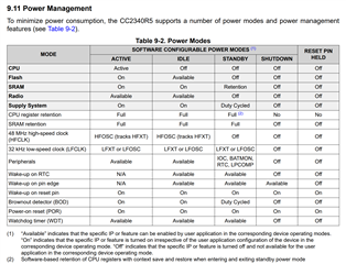
    I also just tested my empty example project with the 8-pin JTAG and noticed the same current as my 3 V + GND wire test. We can reference section 9.11 Power Management to see the power sections to see what blocks the device from entering sleep. 

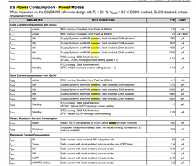
    Also reference section 8.9 Power modes for the specific current totals:

    Thanks,
    Alex F