This thread has been locked.

If you have a related question, please click the "Ask a related question" button in the top right corner. The newly created question will be automatically linked to this question.

CC2340R5-Q1: how to use LIN interfaceto get correct RF signal by HCI cmd in CC2340R5-Q1?

Part Number: CC2340R5-Q1
Other Parts Discussed in Thread: CC2340R5

Hi TI team

    Now we are using LIN interface instead of UART interace in CC2340R5-Q1 for Smart Car Application. And now we have got RSSI from Our CC2340R5-Q1 device by LIN interface.

    One thing we are doing is that how to use LIN interface to test RF performence. We have know that PTM mode can support basic ble image and also HCI cmd, and we have been sure that it can support our RF test by UART interface. Now we have changed the UART interface to LIN interface, and also, we can get the right hci cmd response form LIN interface. But the signal is so many bursts and each burst is spacing 3-8 seconds when we capture signal by Siganl Analyzer. The burst interval is so long, therefore, it caused IQXel-80(Bluetooth RF test equipment) could not capture the signal and the test is fail. Could you please help us review our code or remind us how can get continue signal by LIN interface?

   Thank you so much!

basic_ble_LP_EM_CC2340R5_freertos_ticlang_0520-0315.zip

Best Regards,

Annie

  • Annie,

    TI doesn't have explicit experience interfacing with an RF tester with our device when using the LIN interface so I'm not sure how much feedback we can explicitly provide on your test with LIN but I can ask someone to do a quick review of the software you have linked. Are you sending each device you produce through this test procedure or are you attempting to do functional testing for a subset of select boards? Are you using a LIN stack you have developed or just interfacing with the driver?

  • Hello,

    I have a couple questions before I start reviewing the code:

    1. What specific .c files would you like me to review?

    2. Do you mind elaborating on 'burst'? What signal is being sent?

    3. What HCI commands are you sending?

    Best,

    Nima Behmanesh

  • Hi Evan,

         We are attempting to do functional testing for a subset of select boards and if it is successful, we will have a Mass production testing by this way.  And LIN stack is developed by our SW workmate.

  • Hi Nima,

         1. We add a lin interface in Basic Ble PTM project. And it is our code which developed by our SW workmated. And .c file is as below

    npi_tl_lin.c
    #if (defined(HCI_TL_FULL) || defined(PTM_MODE))
    /******************************************************************************
    
     @file  npi_tl_uart.c
    
     @brief NPI Transport Layer Module for UART
    
     Group: WCS, LPC, BTS
     Target Device: cc23xx
    
     ******************************************************************************
     
     Copyright (c) 2015-2023, Texas Instruments Incorporated
     All rights reserved.
    
     Redistribution and use in source and binary forms, with or without
     modification, are permitted provided that the following conditions
     are met:
    
     *  Redistributions of source code must retain the above copyright
        notice, this list of conditions and the following disclaimer.
    
     *  Redistributions in binary form must reproduce the above copyright
        notice, this list of conditions and the following disclaimer in the
        documentation and/or other materials provided with the distribution.
    
     *  Neither the name of Texas Instruments Incorporated nor the names of
        its contributors may be used to endorse or promote products derived
        from this software without specific prior written permission.
    
     THIS SOFTWARE IS PROVIDED BY THE COPYRIGHT HOLDERS AND CONTRIBUTORS "AS IS"
     AND ANY EXPRESS OR IMPLIED WARRANTIES, INCLUDING, BUT NOT LIMITED TO,
     THE IMPLIED WARRANTIES OF MERCHANTABILITY AND FITNESS FOR A PARTICULAR
     PURPOSE ARE DISCLAIMED. IN NO EVENT SHALL THE COPYRIGHT OWNER OR
     CONTRIBUTORS BE LIABLE FOR ANY DIRECT, INDIRECT, INCIDENTAL, SPECIAL,
     EXEMPLARY, OR CONSEQUENTIAL DAMAGES (INCLUDING, BUT NOT LIMITED TO,
     PROCUREMENT OF SUBSTITUTE GOODS OR SERVICES; LOSS OF USE, DATA, OR PROFITS;
     OR BUSINESS INTERRUPTION) HOWEVER CAUSED AND ON ANY THEORY OF LIABILITY,
     WHETHER IN CONTRACT, STRICT LIABILITY, OR TORT (INCLUDING NEGLIGENCE OR
     OTHERWISE) ARISING IN ANY WAY OUT OF THE USE OF THIS SOFTWARE,
     EVEN IF ADVISED OF THE POSSIBILITY OF SUCH DAMAGE.
    
     ******************************************************************************
     
     
     *****************************************************************************/
    
    // ****************************************************************************
    // includes
    // ****************************************************************************
    #ifdef FREERTOS
    #include <FreeRTOS.h>
    #include <task.h>
    #include <mqueue.h>
    #include <stdarg.h>
    #else
    #include <ti/sysbios/knl/Task.h>
    #include <ti/sysbios/knl/Swi.h>
    #include <xdc/std.h>
    #if defined( CC13X4 )
    #include <ti/sysbios/family/arm/v8m/Hwi.h>
    #else
    #include <ti/sysbios/family/arm/m3/Hwi.h>
    #endif
    #endif
    #include <string.h>
    #include <ti/devices/DeviceFamily.h>
    #include DeviceFamily_constructPath(inc/hw_memmap.h)
    #include DeviceFamily_constructPath(inc/hw_ints.h)
    #include "icall.h"
    #include <ti_drivers_config.h>
    #include "hal_types.h"
    #include <ti/drivers/Power.h>
    
    #include "inc/npi_config.h"
    #include "inc/npi_tl_uart.h"
    #include <ti/drivers/UART2.h>
    #ifdef CC23X0
    #include <ti/drivers/uart2/UART2LPF3.h>
    #else
    #include <ti/drivers/uart2/UART2CC26X2.h>
    #endif
    #include <ti/devices/DeviceFamily.h>
    #include DeviceFamily_constructPath(driverlib/uart.h)
    #include <ti/drivers/timer/LGPTimerLPF3.h>
    
    // ****************************************************************************
    // defines
    // ****************************************************************************
    
    // ****************************************************************************
    // typedefs
    // ****************************************************************************
    
    //*****************************************************************************
    // globals
    //*****************************************************************************
    //! \brief UART Handle for UART Driver
    static UART2_Handle uartHandle;
    
    //! \brief UART ISR Rx Buffer
    static Char isrRxBuf[UART_ISR_BUF_SIZE];
    
    //! \brief NPI TL call back function for the end of a UART transaction
    static npiCB_t npiTransmitCB = NULL;
    
    #if (NPI_FLOW_CTRL == 1)
    //! \brief Flag signalling receive in progress
    static uint8 RxActive = FALSE;
    
    //! \brief Flag signalling transmit in progress
    static uint8 TxActive = FALSE;
    
    //! \brief Value of MRDY NPI TL pin
    static uint8 mrdy_flag = 1;
    #endif // NPI_FLOW_CTRL = 1
    
    //! \brief Pointer to NPI TL TX Buffer
    static Char* TransportRxBuf;
    static Char* TransportRxBufTemp;
    static uint16 TransportRxLenTemp = 0;
    //! \brief Length of bytes received
    static uint16 TransportRxLen = 0;
    
    //! \brief Pointer to NPI TL RX Buffer
    static Char* TransportTxBuf;
    
    //! \brief Length of bytes to send from NPI TL Tx Buffer
    static uint16 TransportTxLen = 0;
    
    //! \brief This flag indicates that all the data has been fully transmitted from the UART
    static uint8 UartTxFinishedFlag = FALSE;
    
    //! \brief UART Object. Initialized in board specific files
    #ifdef CC23X0
    extern UART2LPF3_Object uart2LPF3Objects[];
    #else
    extern UART2CC26X2_Object uart2CC26X2Objects[];
    #endif
    
    bool isRequest;
    
    //*****************************************************************************
    // function prototypes
    //*****************************************************************************
    
    //! \brief UART ISR function. Invoked upon specific threshold of UART RX FIFO size
    static uint16 NPITLUART_readIsrBuf(size_t size);
    
    //! \brief UART Callback invoked after UART write completion
    static void NPITLUART_writeCallBack(UART2_Handle handle, void *ptr, size_t size, void *userArg, int_fast16_t status);
    
    //! \brief UART Callback invoked after event has occurred.
    static void NPITLUART_eventCallBack(UART2_Handle handle, uint32_t event, uint32_t data, void *userArg);
    
    //! \brief UART Callback invoked after readsize has been read or timeout
    static void NPITLUART_readCallBack(UART2_Handle handle, void *ptr, size_t size, void *userArg, int_fast16_t status);
    extern uint8_t LIN_MakeChecksumByte(const uint8_t *buffer, uint8_t sizeBuffer, uint8_t PID);
    
    // -----------------------------------------------------------------------------
    //! \brief      This routine initializes the transport layer and opens the port
    //!             of the device.
    //!
    //! \param[in]  tRxBuf - pointer to NPI TL Tx Buffer
    //! \param[in]  tTxBuf - pointer to NPI TL Rx Buffer
    //! \param[in]  npiCBack - NPI TL call back function to be invoked at the end of
    //!             a UART transaction
    //!
    //! \return     void
    // -----------------------------------------------------------------------------
    void NPITLUART_initializeTransport(Char *tRxBuf, Char *tTxBuf, npiCB_t npiCBack)
    {
    
        TransportRxBuf = tRxBuf;
        TransportTxBuf = tTxBuf;
        TransportRxBufTemp = (Char *)malloc(660);
        npiTransmitCB = npiCBack;
    
        // Initialize the UART driver
        UART2_Params params;
        UART2_Params_init(&params);
    
        params.readMode = UART2_Mode_CALLBACK;
        params.writeMode = UART2_Mode_CALLBACK;
        params.readCallback = NPITLUART_readCallBack;
        params.writeCallback = NPITLUART_writeCallBack;
        params.eventCallback = NPITLUART_eventCallBack;
        // subscribe to the UART2_EVENT_TX_FINISHED event.
        // The UART2_EVENT_TX_FINISHED event triggered after all of the
        // TX data was transferred from the UART, even when using the DMA.
        params.eventMask |= UART2_EVENT_TX_FINISHED;
    
        params.baudRate = 19200;
        params.dataLength = UART2_DataLen_8;
        params.stopBits = UART2_StopBits_1;
        //debug jing
    //    GPIO_init();
    //    /* Configure the DIO1 pin */
    //    GPIO_setConfig(CONFIG_GPIO_RX_BREAK, GPIO_CFG_IN_PU | GPIO_CFG_IN_INT_FALLING);
    //
    //    /* Install CONFIG_GPIO_RX callback */
    //    GPIO_setCallback(CONFIG_GPIO_RX_BREAK, gpioRXFxn0);
    ////
    //    /* Enable CONFIG_GPIO_RX interrupts */
    //    GPIO_enableInt(CONFIG_GPIO_RX_BREAK);
    //    TIMER_1uS(500);
        isRequest=true;
        //debug jing
    
        // Open / power on the UART.
        uartHandle = UART2_open(CONFIG_DISPLAY_UART, &params);
        if (uartHandle == NULL)
        {
          // An error occured, or indexed UART peripheral is already opened
          HAL_ASSERT( HAL_ASSERT_CAUSE_UNEXPECTED_ERROR );
        }
    
    #if (NPI_FLOW_CTRL == 0)
        // This call will start repeated Uart Reads when Power Savings is disabled
        NPITLUART_readTransport();
    #endif // NPI_FLOW_CTRL = 0
    
        return;
    }
    
    #if (NPI_FLOW_CTRL == 1)
    // -----------------------------------------------------------------------------
    //! \brief      This routine stops any pending reads
    //!
    //! \return     void
    // -----------------------------------------------------------------------------
    void NPITLUART_stopTransfer(void)
    {
        ICall_CSState key;
        key = ICall_enterCriticalSection();
    
        mrdy_flag = 1;
    
        // If we have no bytes in FIFO yet we must assume there was nothing to read
        // or that the FIFO has already been read for this UART_read()
        // In either case UART2_readCancel will call the read CB function and it will
        // invoke npiTransmitCB with the appropriate number of bytes read
    #ifdef CC23X0
        if (!UARTCharAvailable(((UART2LPF3_HWAttrs const *)(uartHandle->hwAttrs))->baseAddr))
    #else
        if (!UARTCharsAvail(((UART2CC26X2_HWAttrs const *)(uartHandle->hwAttrs))->baseAddr))
    #endif
        {
            RxActive = FALSE;
            UART2_readCancel(uartHandle);
        }
    
        ICall_leaveCriticalSection(key);
        return;
    }
    #endif // NPI_FLOW_CTRL = 1
    
    #if (NPI_FLOW_CTRL == 1)
    // -----------------------------------------------------------------------------
    //! \brief      This routine is called from the application context when MRDY is
    //!             de-asserted
    //!
    //! \return     void
    // -----------------------------------------------------------------------------
    void NPITLUART_handleMrdyEvent(void)
    {
        ICall_CSState key;
        key = ICall_enterCriticalSection();
    
        mrdy_flag = 0;
    
        // If we haven't already begun reading, now is the time before Central
        //    potentially starts to send data
        // The !TxActive condition is because we will call UART_npiRead() prior to setting
        // TxActive true. There is the possibility that MRDY gets set high which
        // clears RxActive prior to us getting to this event. This will cause us to
        // read twice per transaction which will cause the transaction to never
        // complete
        if ( !RxActive && !TxActive )
        {
            NPITLUART_readTransport();
        }
    
        // If we have something to write, then the Central has signalled it is ready
        //    to receive. Time to write.
        if ( TxActive )
        {
            // Check to see if transport is successful. If not, reset TxLen to allow
            // another write to be processed
            if ( UART2_write(uartHandle, TransportTxBuf, TransportTxLen, NULL)  != UART2_STATUS_SUCCESS )
            {
              TxActive = FALSE;
              TransportTxLen = 0;
            }
    
        }
    
        ICall_leaveCriticalSection(key);
    
        return;
    }
    #endif // NPI_FLOW_CTRL = 1
    
    // -----------------------------------------------------------------------------
    //! \brief      This callback is invoked after Event has occurred.
    //!
    //! \param[in]  handle - handle to the UART port
    //! \param[in]  event  - UART2_EVENT that has occurred
    //!                    - UART2_EVENT_BREAK
    //!                    - UART2_EVENT_PARITY
    //!                    - UART2_EVENT_FRAMING
    //!                    - UART2_EVENT_TX_BEGIN
    //!                    - UART2_EVENT_TX_FINISHED
    //! \param[in]  data   - accumulated count used for the event UART2_EVENT_OVERRUN
    //!
    //! \return     void
    // -----------------------------------------------------------------------------
    static void NPITLUART_eventCallBack(UART2_Handle handle, uint32_t event, uint32_t data, void *userArg)
    {
      // Check if the UART finished transmitting all the data
      if (event & UART2_EVENT_TX_FINISHED)
      {
          ICall_CSState key = ICall_enterCriticalSection();
    
          // Update UartTxFinishedFlag to TRUE to inform the NPITLUART_writeCallBack function
          // that all the data has been fully transmitted
          UartTxFinishedFlag = TRUE;
          // Call the NPITLUART_writeCallBackto allow backwards compatibility.
          // Unused input params were reset to NULL/0.
          // This function performs the action needed for UART Write
          NPITLUART_writeCallBack(handle, NULL, 0, userArg, 0);
    
          // initialize the UartTxFinishedFlag to FALSE for the next write callBack
          UartTxFinishedFlag = FALSE;
    
          ICall_leaveCriticalSection(key);
      }
    }
    
    // -----------------------------------------------------------------------------
    //! \brief      This callback is invoked on Write completion.
    //!
    //! \param[in]  handle - handle to the UART port
    //! \param[in]  ptr    - pointer to data to be transmitted
    //! \param[in]  size   - size of the data
    //!
    //! \return     void
    // -----------------------------------------------------------------------------
    static void NPITLUART_writeCallBack(UART2_Handle handle, void *ptr, size_t size, void *userArg, int_fast16_t status)
    {
        // Perform the UART write actions only in case all the data has fully
        // transmitted from the UART, and the event UART2_EVENT_TX_FINISHED
        // has received.
        if (UartTxFinishedFlag)
        {
            ICall_CSState key;
            key = ICall_enterCriticalSection();
    
    #if (NPI_FLOW_CTRL == 1)
            if ( !RxActive )
            {
                UART2_readCancel(uartHandle);
                if ( npiTransmitCB )
                {
    
                    npiTransmitCB(TransportRxLen,TransportTxLen);
                }
            }
            TxActive = FALSE;
    #else
            if ( npiTransmitCB )
            {
                npiTransmitCB(0,TransportTxLen);
            }
            #endif // NPI_FLOW_CTRL = 1
            TransportRxLenTemp=0;
    
            ICall_leaveCriticalSection(key);
        }
    }


    // -----------------------------------------------------------------------------
    //! \brief      This callback is invoked on Read completion of readSize/receive
    //!             timeout
    //!
    //! \param[in]  handle - handle to the UART port
    //! \param[in]  ptr    - pointer to buffer to read data into
    //! \param[in]  size   - size of the data
    //!
    //! \return     void
    // -----------------------------------------------------------------------------
    static void NPITLUART_readCallBack(UART2_Handle handle, void *ptr, size_t size, void *userArg, int_fast16_t status)
    {
        ICall_CSState key;
        key = ICall_enterCriticalSection();
        if (size)
        {
            if (size != NPITLUART_readIsrBuf(size)+1)
            {
                // Buffer overflow imminent. Cancel read and pass to higher layers
                // for handling
    #if (NPI_FLOW_CTRL == 1)
                RxActive = FALSE;
    #endif // NPI_FLOW_CTRL = 1
                if ( npiTransmitCB )
                {
                    npiTransmitCB(NPI_TL_BUF_SIZE,TransportTxLen);
                }
            }
    
        }
    
    #if (NPI_FLOW_CTRL == 1)
        // Read has been cancelled by transport layer, or bus timeout and no bytes in FIFO and in circular buffer
        //    - do not invoke another read
    #ifdef CC23X0
        if (!UARTCharAvailable(((UART2LPF3_HWAttrs const *)(uartHandle->hwAttrs))->baseAddr) &&
    #else
        if (!UARTCharsAvail(((UART2CC26X2_HWAttrs const *)(uartHandle->hwAttrs))->baseAddr) &&
    #endif
           (UART2_getRxCount(uartHandle) == 0) &&
            mrdy_flag )
        {
            RxActive = FALSE;
    
            // If TX has also completed then we are safe to issue call back
            if ( !TxActive && npiTransmitCB )
            {
                npiTransmitCB(TransportRxLen,TransportTxLen);
            }
        }
        else
        {
            UART2_read(uartHandle, &isrRxBuf[0], UART_ISR_BUF_SIZE, NULL);
        }
    #else
        if ( npiTransmitCB )
        {
            npiTransmitCB(size,0);
        }
    
    //    if (TransportRxLen==0)
    //    {
            UART2_read(uartHandle, &isrRxBuf[0], UART_ISR_BUF_SIZE, NULL);
            TransportRxLen = 0;
    //    }
    
    
    #endif // NPI_FLOW_CTRL = 1
    
        ICall_leaveCriticalSection(key);
    }
    
    // -----------------------------------------------------------------------------
    //! \brief      This routine reads data from the transport layer based on len,
    //!             and places it into the buffer.
    //!
    //! \param[in]  size - amount of bytes in UART ISR Rx Buffer
    //!
    //! \return     uint16 - number of bytes read from transport
    // -----------------------------------------------------------------------------
    static uint16 NPITLUART_readIsrBuf(size_t size)
    {
        uint8_t i = 0;
    
        // Copy the UART buffer to the application buffer
        // Do not allow overflow of buffer. Instead pass up to NPI module and allow
        // it to handle
        if(isrRxBuf[0]==0U &&isrRxBuf[1]==0x55U)
        {
            switch (isrRxBuf[2]){
    
                case 0x50U: /* ID 0x10 */
                    TransportRxLenTemp=0;
                    for (int c=0;c<TransportTxLen;c++)
                    {
                        TransportTxBuf[c]=0;
                    }
                    for (i=3; (i < size-1) && (TransportRxLenTemp < NPI_TL_BUF_SIZE); i++)
                    {
                        TransportRxBufTemp[TransportRxLenTemp++] = isrRxBuf[i];
    //                    TransportRxBuf[TransportRxLen++] = isrRxBuf[i];
                    }
    
    
                    for (i=0; i < size; i++)
                    {
                        isrRxBuf[i] = 0;
                    }
                    isRequest=true;
                    i= 0;
                    break;
                case 0x11U:
                    isRequest=false;
    
                    for (i=0; (i < TransportRxLenTemp-1) && (TransportRxLen < NPI_TL_BUF_SIZE); i++)
                    {
                        TransportRxBuf[TransportRxLen++] = TransportRxBufTemp[i];
                        TransportRxBufTemp[i]=0;
                        isrRxBuf[i] = 0;
                    }
    //                TransportRxLen=4;
    //                TransportRxBuf[0]=0x01;
    //                TransportRxBuf[1]=0x03;
    //                TransportRxBuf[2]=0x0c;
    //                TransportRxBuf[3]=0x00;
    //                TransportRxLen=4;
    //                for (i=3; (i < size-1) && (TransportRxLen < NPI_TL_BUF_SIZE); i++)
    //                {
    //                    TransportRxBuf[TransportRxLen++] = isrRxBuf[i];
    //                    isrRxBuf[i] = 0;
    //                }
                    i=size-1;
                    break;
                default:
                    break;
            }
    
            for (int c=0;c<3;c++)
            {
                isrRxBuf[c]=0;
            }
    
        }else{
            for (i=0; i < size; i++)
            {
                isrRxBuf[i] = 0;
            }
            isRequest=false;
            i=0;
        }
    
        return i;
    
    }
    
    // -----------------------------------------------------------------------------
    //! \brief      This routine reads data from the UART
    //!
    //! \return     void
    // -----------------------------------------------------------------------------
    void NPITLUART_readTransport(void)
    {
        ICall_CSState key;
        key = ICall_enterCriticalSection();
    
    #if (NPI_FLOW_CTRL == 1)
        RxActive = TRUE;
    #endif // NPI_FLOW_CTRL = 1
        TransportRxLen = 0;
        UART2_read(uartHandle, &isrRxBuf[0], UART_ISR_BUF_SIZE, NULL);
    
        ICall_leaveCriticalSection(key);
    }
    
    
    // -----------------------------------------------------------------------------
    //! \brief      This routine writes copies buffer addr to the transport layer.
    //!
    //! \param[in]  len - Number of bytes to write.
    //!
    //! \return     uint8 - number of bytes written to transport
    // -----------------------------------------------------------------------------
    uint16 NPITLUART_writeTransport(uint16 len)
    {
        ICall_CSState key;
        key = ICall_enterCriticalSection();
    
        TransportTxLen = len;
    
    #if (NPI_FLOW_CTRL == 1)
        TxActive = TRUE;
    
        // Start reading prior to impending write transaction
        // We can only call UART_write() once MRDY has been signaled from Central
        // device
        NPITLUART_readTransport();
    #else
        // Check to see if transport is successful. If not, reset TxLen to allow
        // another write to be processed
        if (TransportRxLenTemp !=0){
            TransportTxBuf[TransportTxLen] = LIN_MakeChecksumByte(&TransportTxBuf[2], TransportTxLen-2, 0x11);
            TransportTxLen = TransportTxLen+1;
            if(UART2_write(uartHandle, &TransportTxBuf[2], TransportTxLen-2, NULL) != UART2_STATUS_SUCCESS)
            {
              TransportTxLen = 0;
            }
        }
    
    #endif // NPI_FLOW_CTRL = 1
        ICall_leaveCriticalSection(key);
    
        return TransportTxLen;
    }
    #endif// HCI_TL_FULL || PTM_MODE
    

        2. And signal behavior is as below video.

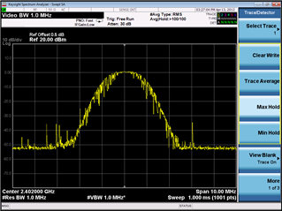
    by lin ininterface, SA set clear write, and I took a video like below, it seems no signal:

    But I set SA to Max hold, it did have signal here like below picture,

    And I change change the default basic ble PTM image whose interface is UART, and I got signal video like below, it is easily to capture:

    3. for Lin interface, when I power up The DUT and did not send hci cmd, it have the sigal like I described point 2.

    But I still send HCI cmd:

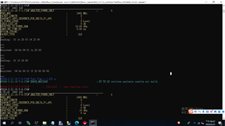
    send>>01 1e 20 03 00 25 00
    response<<04 0e 04 01 1e 20 00

    it keep the same signal.

    Best Regards,

    Annie

  • Hi Nima,

       We tried to fix the code, and now we we got more mormal wave with HCI cmd by LIN interface. But Our IQxel-80 could not analyze the signal by auto Procedure, it really confused us. We guess maybe it need more time to tranfer data by LIN interface. So IQxel-80could not analyze the data.

    IQxel-80 test result:

    So if you have any idea about how to decrease LIN transfer time? Or any ideas about this topic I post, we are willing to wait for your sharing.

    Best Regards

    Annie

  • Hello,

    I'm not quite sure I can comment on anything to decrease the LIN transfer time. From my understanding, the LIN driver you are using is written by a third-party, so we don't have much control on its implementation or have its details.

    If you have specific questions about the device or our supported drivers, I'd be happy to answer those. 

    Best,

    Nima Behmanesh

  • Hi Nima,

       Yeah, I got. I will search the Equipment engineer fo help, and still thank you so much.

       And this morning, I found a new issue. We use Basic_Ble_PTM image+Lin interface to send 2442MHz/2480Mhz signal, and use SA to anerlayze, its output is 2402Mhz/ 2464Mhz signal. Like below pictrue:

    cmd:

    01 1e 20 03 14 25 00

    Recieve<<04 0e 04 01 1e 20 00

    Output:

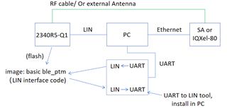
    Our setting is like below picture:

    2340R5-Q1 flashed basic ble_ptm(Lin interface code), by UART to Lin tool, which is installed in PC, then recieve and transfer HCI data to send sigal.

    We have compared the HCI cmd between basic ble_ptm(Lin interface code) and basic ble_ptm(UART interface code), it can get the same cmd. Only the basic ble_ptm(Lin interface code) output the uncorrect signal.

    So If you know Why we could not recieve correct signal here, would mind reminding us?

    Sorry for taking your time.

    Best Regards,

    Annie