This thread has been locked.

If you have a related question, please click the "Ask a related question" button in the top right corner. The newly created question will be automatically linked to this question.

CC2340R5-Q1: How to Enable Flash Memory Protection

Part Number: CC2340R5-Q1
Other Parts Discussed in Thread: UNIFLASH, CC2340R5, , SYSCONFIG

Tool/software:

Hi, Ti

How to Enable Flash Memory Protection?

My factory data flash area ranges from 0x7F000 to 0x80000.This area is not allowed to be erased.

First, I write the factory data to the above area by NVS_write().

Then I commented out the code related to operating the nvs and re-flashed.This area is still restored to 0xFF even after I enable flash protection.

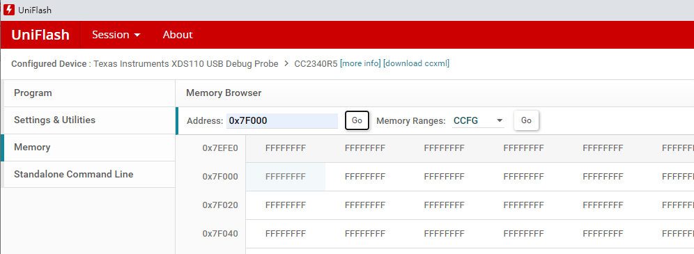
My Flash Protection Settings are shown in the image below:

Can I ask if there is a misconfiguration that is causing the sectors not to be reserved? My understanding is that by changing the data in the Erase/Retain, Main Sectors 32-255 option, corresponding to the sector indicator bit to 1, this sector will be protected.

Best Regards

Preston

  • Hello Preston,

    I am currently looking into your question and will provide a more thorough response Wednesday. In the meantime, please refer to sections 8.3.2.3.1, and 8.2.4.2 in the CC23xx Technical Reference Manual for more information on the flash retention feature.

    Additionally, in the future, please refrain from creating separate E2E threads for the same question. 

    Thanks, 

    Isaac

  • Hi, 

    Additionally, in the future, please refrain from creating separate E2E threads for the same question. 

    I'll take care of that next time.

    From reading the TRM section, I think uniflash using the SACI command to process image updates.

    I have some question that I need you to clarify.

    1.When I update the image using uniflash, selecting the Chip Erase (Retain sectors specified in CCFG) option causes the load to fail.

    The first time the update succeeded with Chip Erase selected, the second time with Chip Erase selected (Retain sectors specified in CCFG) it failed.

    What's the reason for this?

    2.Do I have to select Chip Erase (Retain sectors specified in CCFG) if I want to retain the specified sectors? Will selecting Chip Erase cause the flash protection setting to fail? It seems so from the contents of the parentheses.

    Please help me make sense of these two issues.

    Best Regards

    Preston

  • Hello Preston, 

    I apologize for the delay. I am waiting on a response from an individual about the issue, unfortunately he is currently sick. I hope to have a response by the end of this week but will keep you updated. 

    In the meantime, what SDK and uniflash version are you using, and you are using the NVSInternal example project correct? 

    Thanks, 

    Isaac

  • Hi, 

    what SDK and uniflash version are you using

    SDK:simplelink_lowpower_f3_sdk_7_40_00_64

    uniflash:8.4.0.4458

    and you are using the NVSInternal example project correct? 

    Yes, I'm doing nvs writes via the NVSInternal example project.

    Best Regards

    Preston

  • Hello Preston, 

    First recommendation is to update Uniflash to version 8.6. 

    Please test your setup with the project I have provided. I was able to alter NVSInternal to retain 0x7F000-0x80000, when CCFG protections are on in Uniflash. Within the code, I set the Main Sectors 32-255 to 0x0800 0000, flashed the device to write to memory, read the memory to verify the memory was written, re-flashed the device with the same program, but without the write command, and having turned on Chip Erase (Retain sectors specified in CCFG). This retained the flash. 

    NVSInternal_RetainFlashSectors.zip

    Please test my project, and your project on Uniflash 8.6. 

    Let me know if anything doesn't work, or if you have any more questions!

    Thanks, 
    Isaac 

  • Hi, 

    I used the project you provided for testing.And then I ran into some problems.

    1. When I select Chip Erase (Retain sectors specified in CCFG), I can't re-flash it.

    If I change to selecting Chip Erase with all other conditions unchanged, I can re-flash successfully.

    2. I also tried re-flashing using J-link, and looking through the tool it doesn't write or erase 0x7F000-0x80000, but the contents of 0x7F000-0x80000 still  0xFF. What is the reason for this? If I want to enable the flash protection can I use J-link? 

    Please help me with these two questions,Thanks.

    Best Regards

    Preston

  • Hi, 

    Add some info, I've updated the uniflash and sdk.

    uniflash:8.6.0.4688

    sdk:8.10.00.55

    Best Regards

    Preston

  • Hello Preston, 

    Can you try flashing with CCS, then reading the memory on Uniflash? 

    Additionally, can you try using a different CC2340R5 board, and/or a different XDS110? 

    I will attach my updated project for SDK 8.10.00.55, with the working flash retention. 

    NVSInternal_RetainFlashSectors2.zip

    Again, please test this program by first flashing with the NVS_write() function writing to the desired address. Then comment out the NVS_write() function and reflash on uniflash using Chip Erase (Retain sectors specified in CCFG). Alternatively, you can reflash the device from CCS using Chip Erase (Retain sectors specified in CCFG), by going to Run -> Debug Configurations -> Target -> Flash Settings -> select Chip Erase (Retain sectors specified in CCFG)

    Let me know if this works, or if you have additional questions! 

    Thanks,

    Isaac

  • Hi, 

    I would try re-flashing with ccs and uniflash and try multiple boards.

    Also, can you help me with the second issue (updating using Jlink)? This will involve our production process (What software to use for re-flashing).

    Best Regards

    Preston

  • Hello Preston, 

    Please let me know if the project works! 

    Additionally, please check if completing a chip erase on Uniflash before attempting the flashing process helps.

    I believe that flash protection can be used with J-Link, but I am currently waiting on verification of this.

    Let me know if the chip erase or the project provided works! 

    Thanks, 

    Isaac 

  • Hi, 

    We had two models of cc2340 (CC2340R5 and CC2340R5 Q1) and then did the relevant verification

    CC2340R5(demo board):

    1.Re-flashing with ccs allows normal use of flash protection

    2.Re-flashing with uniflash allows normal use of flash protection

    3.Flash protection failure after re-flash with J-link(Using J-Flash V7.92o, deselect 0x7F000-0x7FFFF, deselect means J-link does not erase unselected area)

    CC2340R5-Q1(Self-developed boards):

    1.Re-flashing with ccs allows normal use of flash protection

    2.Memory cannot be reflashed by selecting Chip Erase (Retain sectors specified in CCFG).

    3.Flash protection failure after re-flash with J-link

    Are there any differences between CC2340R5 and CC2340R5-Q1 when reflashing memory using uniflash?

    Best Regards

    Preston

  • Hello Preston, 

    It is good to hear that the demo is working on uniflash for CC2340R5! 

    For J-Link, I am still waiting on information about the flash retention feature. I am assuming you are using IAR with the J-Link debugger? If so, flash retention can be used in IAR. I will update you with more information Wednesday. 

    For the CC2340R5-Q1, are you seeing the same error when flashing as the previous uniflash flash error? Did you switch the pin configuration from the CC2340R5 to the CC2340R5-Q1? To do this navigate to SysConfig -> Show Device View -> Switch -> Board, New Value -> Select CC2340R5 Q1 Development

    Please change this and re-attempt the flashing. Additionally, try flashing on CCS and Uniflash to test, I observed both methods working with the CC2340R5-Q1. 

    Thanks, 
    Isaac

  • Hi, 

    Still can't re-flash on uniflash after change pin configuration.

    May I ask what file extension you re-flashed? I tried .out, .hex(ASCII hex), .bin.

    Also since it's a Self-developed boards,we connect TCK, TMS and GND to the XDS110 with DuPont wires.Does this satisfy the hardware re-flash condition?

    Best Regards

    Preston

  • Hello Preston, 

    I am using a .out file to flash on Uniflash. 

    Are you powering the board externally or through the XDS110? The minimum required connections include SWDIO (TMS), SWDCK (TCK), GND, and 3.3v. If the board is powered externally, the 3.3v from the XDS-110 is not needed. For more information, please reference the Introduction to the SimpleLink Low Power F3 SDK section of the User's Guide. 

    Additionally, flash protection is not supported with the use of J-Link debuggers. 

    Did you attempt to re-flash the device using CCS? Could this be a potential problem with the custom hardware? 

    Let me know! 

    Thanks, 

    Isaac

  • Hi, 

    I'm using an external power supply, and the connections to the XDS-110 are SWDIO (TMS), SWDCK (TCK), and GND. The flash memory can be re-flashed properly using CCS and the flash protection works properly.

    What is the difference between using CCS and uniflash? Is it possible to have problems with CRC checksums and such? I'll have the hardware check it out, too.

    Also, can you tell me why the Jlink debugger doesn't support it? Thanks !

    Best Regards

    Preston

  • Hi, 

    Newsflash, I found a way to reflash, I need to hold down the reset button, click on “Load Image” and then let go and it will download!

    I suspect that it couldn't get into download mode before?

    Also, I would like to ask how to use command line reflash(flash protect) and do I need to create another new E2E thread for this issue?

    Best Regards

    Preston

  • Hello Preston, 

    Glad to hear you were able to flash the board! 

    TI supports the use of J-Link debuggers, but some features are not available. I am not sure if this is something that will be added in the future, but I will check. 

    I am not sure why holding the reset button allowed Uniflash to flash the image. I recommend having the custom design reviewed for possible issues in general and with the reset line. Be sure to let the hardware team know about the behavior associated with the reset line and flashing on Uniflash. 

    There is no difference in the way CCS and Uniflash flash the software image.

    Yes, please create another E2E thread for the new question. 

    Thanks, 

    Isaac