This thread has been locked.

If you have a related question, please click the "Ask a related question" button in the top right corner. The newly created question will be automatically linked to this question.

CC2642R: Undefined symbol CONFIG_DISPLAY_UART in the TI file npi_tl_uart.c

Part Number: CC2642R
Other Parts Discussed in Thread: SYSCONFIG, UNIFLASH

Tool/software:

Hi Clément, or other TI support guru,

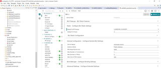
I am trying to use DTM mode by selecting PTM in sysconfig, and including the NPI files in the build (attached screenshot below):

During the build I get an undefined symbol CONFIG_DISPLAY_UART in the TI file npi_tl_uart.c , line 163:
uartHandle = UART_open(CONFIG_DISPLAY_UART, &params);

I can resolve the undefined symbol CONFIG_DISPLAY_UART  by changing this TI .c file npi_tl_uart.c: use directly index 0 (UART0) as the first UART_open() actual parameter.
I am trying to find a better solution. I could not find an include file for the above undefined symbol. Also: I do not want to change a TI file in principle.

  • Hi,

    Thank you for reaching the support,

    Could you share which example and SDK you are using?

    Regards,
    Tanguy

  • Hi Tanguy,

    We are using SDK: simplelink_cc13xx_cc26xx_sdk_6_10_00_29

    We declared in sysconfig: RF based on LAUNCHXL:


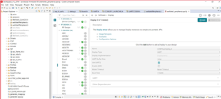
    We do not have a physical display in our custom PCBA, so we excluded the Display in sysconfig:

    Why do we have undefined symbol CONFIG_DISPLAY_UART in the TI SDK file npi_tl_uart.c , line 16 ?

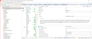
  • We managed to resolve the undefined symbol and build OK, by adding Display in the sysconfig file with display name same as the undefined symbol: CONFIG_DISPLAY_UART

  • Screenshot from the updated sysconfig file:

  • I am now trying to test DTM mode following link: 
    software-dl.ti.com/.../ptm-and-dtm.html

    I am looking at the Translation tables in icall_hci_tl.c . Any suggestions how to test DTM mode will be welcomed.

  • Hi Ludmil,

    I am not sure to correctly understand what you mean by DTM mode, could you be more specific?

    For more details about radio testing you can check this Application note: How to Do RF Radio Test With Your Bluetooth Product

    Regards,
    Tanguy

  • Hi Tanguy, I provided a link above to the TI DTM description, copy here as well:

    software-dl.ti.com/.../ptm-and-dtm.html

  • Hi Ludmil,

    Please find here the Configuring Bluetooth LE devices for Direct Test Mode (ti.com) application note.

    I hope this will help,
    Regards

  • Thanks a lot, I am trying to use this note, but this note is using:
    The SimplelinkTm Software Development Kit (SDK): – CC13x2 and CC26x2 – CC2640R2

    Our SDK is 
    SimpleLink CC13xx CC26xx SDK version 6.10.00.29

  • I am trying the hex file referenced in the doc you provided:
    CC13xx/26xx: C:\ti\simplelink_cc13xx_26xx_sdk_M_mm_mm_mm\examples\rtos\\ble5stack\hexfiles\host_test_app.hex

  • Hi Ludmil,

    There was a change in the SDK naming and the The SimplelinkTm Software Development Kit (SDK): – CC13x2 and CC26x2 is the same as the cc13xx_26xx,

    Regards,
    Tanguy

  • Hi Tanguy,
    Thanks for the information. We re using SDK cc13xx_26xx, I am still trying to get DTM running well.
    I had compilation problems: NPI_MAX_FRAG_SIZE was undefined. I found a place in one SDK file: npi_config.h: Word "defined" missing in the source code: line 122: see attached below. 

    I added "defined", the pre-processor started working OK, NPI_MAX_FRAG_SIZE is no longer undefined, and all compiled OK, see below:

  • Hi Tanguy, Our SDK is simplelink_cc13xx_cc26xx_sdk_6_10_00_29.

    I cannot run successful basic PTM / DTM tests using manual commands on the serial port. This is valid for all 3 configuration (firmware app) types shown below. I will appreciate any help to run basic DTM tests over UART because DTM is high priority for us now. I do not have specialized DTM test equipment.

    The 3 configuration (firmware app) types I tried so far, are:
    1) Our Firmware (FW) app:
    In PTM mode, I run the following 2 APIs successfully in our FW application code after initialization (As a PTM / DTM test, I check advertising with a mobile app and see reset action):
    HCI_LE_SetAdvEnableCmd(1);    // Start advertising

    HCI_EXT_ResetSystemCmd(0); // LL_EXT_RESET_SYSTEM_HARD

    In PTM mode, however, I cannot run successfully the above 2 APIs as commands on the serial port controlled by NPI. I type manually the following 2 equivalent commands:
    HCI_LE_SetAdvEnableCmd 1
    HCI_EXT_ResetSystemCmd 0

    Our FW app has the following setup:
    1. Selected PTM in sysconfig file (in the BLE/Advanced section)
    2. In the syscfg file: UART0 and NPI both do NOT have flow control ticked, also removed Power management
    3. Added PTM_MODE and NPI_USE_UART to the predefined symbols in the CCS project
    4. Removed POWER_SAVING from the predefined symbols in the CCS project
    5. Included all NPI files in the build
    6. I use UART name: CONFIG_DISPLAY_UART in sysconfig file for the UART0 (same as the host test TI example app)

    2) host_test_app supplied by TI: source code: project host_test_CC26X2R1_LAUNCHXL_tirtos_cc
    Setup in the predefined symbols: added NPI_USE_UART
    File build_config.opt has HCI_TL_FULL in the setup, not PTM option. I probably need to try PTM instead of HCI_TL_FULL?

    3) host_test_app.hex: As per TI Application note, I tried to use:
    C:\ti\simplelink_cc13xx_cc26xx_sdk_6_10_00_29\examples\rtos\CC26X2R1_LAUNCHXL\ble5stack\hexfiles\host_test_app.hex
    (Loaded using Uniflash).

  • Hi Ludmil,

    Change to PTM were made in the newest SDK releases, can you try again enabling PTM in the SDK 7.41.00.17?

    Regards,
    Tanguy

  • Hi Tanguy,
    Thanks, In order to use this new SDK 7.41.00.17, do we need to switch to TIRTOS 7 ?

  • Hi Tanguy,
    Thanks for the migration info, this will take time to do. I found another solution: use the available host_test TI source code project or .hex files, but they seem to have a fixed range for UART digital inputs and outputs allowed to be used: 2,3, and 4: screenshot below. Do you know how I can change these in the sysconfig file to use our digital Input and Output fixed on our PCBA as 15 and 16?

  • Hi Ludmil,

    Can you try to follow these steps:

    1. Remove CONFIG_Display_0
    2. In UART set Use Hardware to None
    3. You should be able to use different pins for the UART driver.

    Regards,
    Tanguy

  • Thanks Tanguy,
    I followed your advice: steps 1,2,3 above: It did not compile initially, to resolve this I replaced CONFIG_UART_0 with CONFIG_DISPLAY_UART
    added NPI_USE_UART to Project properties/predefined symbols.
    HCI_TL_FULL was the only option that built OK for this host test application: I loaded the build on our Activbody device, connected to the device on the serial port, and sent DTM test commands in binary format following the link:
    software-dl.ti.com/.../hci_interface.html

    I did not get back any binary responses from the NPI task on the serial port.

    I also ran our firmware application in PTM/DTM mode on the same device and received some responses back, I used the following setup:
    1. Selected PTM in sysconfig file (in the BLE/Advanced section)
    2. In the syscfg file: UART0 and NPI both do NOT have flow control ticked, also removed Power management
    2a. In the syscfg file: Set ICALL_MAX_NUM_TASKS=4 (3 => 4 increased manually)
    3. Added PTM_MODE and NPI_USE_UART to the predefined symbols in the CCS project
    4. Removed POWER_SAVING from the predefined symbols in the CCS project
    5. Included all NPI files in the build
    6. Set UART name: CONFIG_DISPLAY_UART in syscfg file.

    . With this setup I got echo binary responses:
    I used a script to send several DTM commands to our device running our app: each command had 2 bytes in binary format, for example:
    0x2006 #Set adv params
    0x1009 #Read BD address

    For each command sent, I obtained a response back: echo of the command on the serial port, ie. received the same 2 bytes as the command sent in binary. Is this expected as part of DTM communication? 

    I looked at the Bluetooth Org spec: BLUETOOTH CORE SPECIFICATION Version 5.2 | Vol 6, Part F and found in section 3.4.1:
    LE_Test_Status event packet: 2 byte binary response 0x0000. Is this the correct DTM response that I should expect?
     

  • Hi Ludmil,

    You can verify the DTM response by using BTool to send the command and check if it's able to parse the response? Find more details about BTool under RF Testing using BTool in the User's Guide.

    Additionally, the UART driver is fully deprecated and has been removed in favor of UART2 since the 6.40.00.13 SDK. If you use the host_test example, make sure to use SDK 6.40.00.13 or newer.

    Regards,
    Tanguy

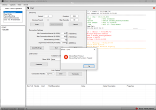
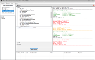
  • Thanks Tanguy, I tried to use the BTool under Windows 10 after loading my .hex file image on our device. I got an error back, details:
    I connected on the serial port and got back the attached error: 1st reset command to the device: no expected reply from the NPI code. I am trying to debug, but the serial port is used by the Btool:
     

    I used this configuration:
    1. Selected PTM in the sysconfig file (in the BLE/Advanced section)
    2. In the syscfg file: UART0 and NPI both do NOT have flow control ticked, also removed Power management
    2a. In the syscfg file: Set ICALL_MAX_NUM_TASKS=4 (3 => 4 increased manually)
    3. Added PTM_MODE and NPI_USE_UART to the predefined symbols in the CCS project
    4. Removed POWER_SAVING from the predefined symbols in the CCS project
    5. Included all NPI files in the build
    6. Set UART name: CONFIG_DISPLAY_UART in syscfg file.

  • I also followed the Btool user guide and sent HCI_reset command, same result: timeout

  • Hi Ludmil,

    For sanity check could you confirm that your device is well connected on COM7 using the device manager?

    Also are you connecting the uart to the computer with an XDS?

    Additionally, are you using the host_test example as you mentioned in one of your previous messages, if so are you using host_test from the SDK 6.40.00.13 or a newer one?

    Regards,
    Tanguy

  • Yes, I have COM7 good connection (see attached COM screenshot below:


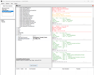
    I also used same COM7 to flash successfully .hex file on the device via XDS110 Debug probe + cable, using the UNIFLASH TI tool. The Btool shows COM7 connected, see attached below:

    If I pull out the USB cable, the Btool gives me an early COM error and does not reach the above send operation in green color in the attached screenshot above.

    I am using my application with PTM mode enabled as per the 6 setup steps I posted above:
    I used this configuration:
    1. Selected PTM in the sysconfig file (in the BLE/Advanced section)
    2. In the syscfg file: UART0 and NPI both do NOT have flow control ticked, also removed Power management
    2a. In the syscfg file: Set ICALL_MAX_NUM_TASKS=4 (3 => 4 increased manually)
    3. Added PTM_MODE and NPI_USE_UART to the predefined symbols in the CCS project
    4. Removed POWER_SAVING from the predefined symbols in the CCS project
    5. Included all NPI files in the build
    6. Set UART name: CONFIG_DISPLAY_UART in syscfg file.

    I will try the host_test example app: host_test from the SDK 6.40.00.13, Is the source code available in SDK 6.40?
    How do I make sure that I get the correct source code of the host test?


  • I installed SDK 6.40.00.13 and found the host test source code, does this SDK require TI RTOS 7?
    I see a sub-folder tirtos7 in the host test folder.

  • Hi Ludmil,

    I confirm the host_test example use TI-RTOS 7,

    Regards,
    Tanguy

  • Thanks Tanguy,

    I configured a CCS project with the new suggested by you: SDK_6.40.0.13 + TI RTOS 7. I set our UART pins in .syscfg, built and flashed on our device, the TI DTM example app "Host Test". I ran it with the TI BTool to send DTM commands to the device. I still observed reset command timeouts and no expected responses shown.
    I get some responses indicating success using our firmware app in PTM mode and a Python program that sends the same byte sequences as BTool.
    I will try latest TI SDK 7.41.00.17 with TI "Host Test" FW app and our FW app.
  • Thanks Tanguy, I tried TI SDK 7.41.00.17 with CCS12 and TI "Host Test" FW app + BTool. I built and flashed a .hex file on our device. Same results as SDK_6.40.0.13: I observed reset command timeouts and no command responses at all shown in the tool: see screenshots below. I expect to see event responses, is this correct? 
    I also used my Python program to send the same byte sequence for commands: I received no response/reply again.


  • In the setup I tried the 3 steps you advised:

    steps:

    1. Remove CONFIG_Display_0
    2. In UART set Use Hardware to None
    3. You should be able to use different pins for the UART driver.

      Also:
      - used replaced CONFIG_UART_0 with CONFIG_DISPLAY_UART to get it to compile.
      - added NPI_USE_UART to Project properties/predefined symbols
      - removed (unticked) Enable policy in Power section in the syscfg file.

      Any other config changes that I need to make? 
      CONFIG_Display_0 is removed now, do I need to remove any source code that tries to open it?
  • Hi Ludmil,

    I manage to change the DTM pin on host_test with SDK 7.40.77 by doing the following:

    1. In SysConfig under CONFIG_DISPLAY I set Hardware to none.
    2. In UART2 I renamed the instance to CONFIG_DISPLAY_UART
    3. Then I changed the pin of the UART2
    4. Finally, I connected DIO18 to the TX pin of an XDS and DIO19 to the RX pin of an XDS

    I notice that if the 2 TX and RX pin are inverted, I have the same issue as you

    Could you sanity check that the settings in SysConfig match your hardware design?

  • Thanks a lot for trying to reproduce the issue. I checked the DIG i/o numbers, I think they are correct: attached below: Tx is 16, Rx is 15 (physical PIN numbers) as we use them on our PCBA and FW app and the UART works.


    I managed to hit UART2_read() breakpoint in the code, but could not see the byte value of "a" in ASCII that I entered on the terminal.
    I was able to see this in our FW days ago, I got replies to commands in our FW (SDK 6.10)

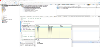
  • Here when debugging the host test, I see that the debugger gets lost when reading:

  • Hi Ludmil,

    I see in your design that UART_RX is set on DIO9 and UART_TX is set on DIO10, could you try to use these pins in SysConfig?

    Regards,
    Tanguy

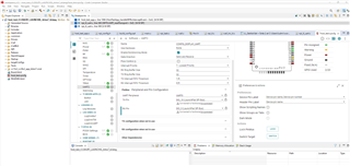
  • It looks like the sysconfig tool user interface has changed for SDK 7.41, so I managed to set the pins as per your request, but had to override/suppress the SPI bus pins set not valid for our PCBA. I had SPI errors in sysconfig, so I removed SPI for host test and then created it with default values.

    I managed to pass the first reset stage, failed on GAPinit:

    Trying to resolve it now

  • Thanks Tanguy, 
    The 2nd and 3rd runs with BTool fully passed the initialization + additional Tx command: log attached. I will test more with Spectrum Analyzer to check the RF.

    Host test SDK 7.41 BTool run log1 OK.txt
    [1] : <Info> - 01:24:29.750
    Port opened at 7/1/2024 1:24:29 PM
    --------------------------------------------------------------------
    [2] : <Tx> - 01:24:29.844
    -Type           : 0x01 (Command)
    -OpCode         : 0xFC1D (HCIExt_ResetSystemCmd)
    -Data Length    : 0x01 (1) byte(s)
     Type           : 0x00 (0) (Chip Reset)
    Dump(Tx):
    0000:01 1D FC 01 00                                  .....
    --------------------------------------------------------------------
    [3] : <Rx> - 01:24:30.221
    -Type           : 0x04 (Event)
    -EventCode      : 0x00FF (HCI_LE_ExtEvent)
    -Data Length    : 0x05 (5) bytes(s)
     Event          : 0x041D (1053) (HCIExt_ResetSystemCmdDone)
     Status         : 0x00 (0) (SUCCESS)
     CmdOpCode      : 0xFC1D (HCIExt_ResetSystemCmd)
    Dump(Rx):
    0000:04 FF 05 1D 04 00 1D FC                         ........
    --------------------------------------------------------------------
    [4] : <Tx> - 01:24:30.756
    -Type           : 0x01 (Command)
    -OpCode         : 0xFE00 (GAP_DeviceInit)
    -Data Length    : 0x08 (8) byte(s)
     ProfileRole    : 0x08 (8) (
                      Central)
     AddrMode       : 0x00 (0) (ADDRMODE_PUBLIC)
     RandomAddr     : 00:00:00:00:00:00
    Dump(Tx):
    0000:01 00 FE 08 08 00 00 00 00 00 00 00             ............
    --------------------------------------------------------------------
    [5] : <Rx> - 01:24:30.835
    -Type           : 0x04 (Event)
    -EventCode      : 0x00FF (HCI_LE_ExtEvent)
    -Data Length    : 0x06 (6) bytes(s)
     Event          : 0x067F (1663) (GAP_HCI_ExtentionCommandStatus)
     Status         : 0x00 (0) (SUCCESS)
     OpCode         : 0xFE00 (GAP_DeviceInit)
     DataLength     : 0x00 (0)
    Dump(Rx):
    0000:04 FF 06 7F 06 00 00 FE 00                      .........
    --------------------------------------------------------------------
    [6] : <Rx> - 01:24:30.851
    -Type           : 0x04 (Event)
    -EventCode      : 0x00FF (HCI_LE_ExtEvent)
    -Data Length    : 0x2C (44) bytes(s)
     Event          : 0x0600 (1536) (GAP_DeviceInitDone)
     Status         : 0x00 (0) (SUCCESS)
     DevAddr        : CC:B5:4C:A7:9C:0C
     DataPktLen     : 0x00FF (255)
     NumDataPkts    : 0x05 (5)
     IRK            : 00:00:00:00:00:00:00:00:00:00:00:00:00:00:00:00
     CSRK           : 36:B7:85:AA:8E:C3:31:E7:AD:0F:26:CE:54:77:2D:18
    Dump(Rx):
    0000:04 FF 2C 00 06 00 0C 9C A7 4C B5 CC FF 00 05 00 ..,......L......
    0010:00 00 00 00 00 00 00 00 00 00 00 00 00 00 00 36 ...............6
    0020:B7 85 AA 8E C3 31 E7 AD 0F 26 CE 54 77 2D 18    .....1...&.Tw-.
    --------------------------------------------------------------------
    [7] : <Tx> - 01:24:30.883
    -Type           : 0x01 (Command)
    -OpCode         : 0xFE61 (GapInit_getPhyParam)
    -Data Length    : 0x02 (2) byte(s)
     PHY            : 0x01 (1) (INIT_PHY_1M)
     ParamId        : 0x02 (2) (INIT_PHYPARAM_CONN_INT_MIN)
    Dump(Tx):
    0000:01 61 FE 02 01 02                               .a....
    --------------------------------------------------------------------
    [8] : <Tx> - 01:24:30.913
    -Type           : 0x01 (Command)
    -OpCode         : 0xFE61 (GapInit_getPhyParam)
    -Data Length    : 0x02 (2) byte(s)
     PHY            : 0x01 (1) (INIT_PHY_1M)
     ParamId        : 0x03 (3) (INIT_PHYPARAM_CONN_INT_MAX)
    Dump(Tx):
    0000:01 61 FE 02 01 03                               .a....
    --------------------------------------------------------------------
    [9] : <Tx> - 01:24:30.929
    -Type           : 0x01 (Command)
    -OpCode         : 0xFE61 (GapInit_getPhyParam)
    -Data Length    : 0x02 (2) byte(s)
     PHY            : 0x01 (1) (INIT_PHY_1M)
     ParamId        : 0x04 (4) (INIT_PHYPARAM_CONN_LATENCY)
    Dump(Tx):
    0000:01 61 FE 02 01 04                               .a....
    --------------------------------------------------------------------
    [10] : <Tx> - 01:24:30.946
    -Type           : 0x01 (Command)
    -OpCode         : 0xFE61 (GapInit_getPhyParam)
    -Data Length    : 0x02 (2) byte(s)
     PHY            : 0x01 (1) (INIT_PHY_1M)
     ParamId        : 0x05 (5) (INIT_PHYPARAM_SUP_TIMEOUT)
    Dump(Tx):
    0000:01 61 FE 02 01 05                               .a....
    --------------------------------------------------------------------
    [11] : <Rx> - 01:24:30.946
    -Type           : 0x04 (Event)
    -EventCode      : 0x00FF (HCI_LE_ExtEvent)
    -Data Length    : 0x09 (9) bytes(s)
     Event          : 0x067F (1663) (GAP_HCI_ExtentionCommandStatus)
     Status         : 0x00 (0) (SUCCESS)
     OpCode         : 0xFE61 (GapInit_getPhyParam)
     DataLength     : 0x03 (3)
     ParamId        : 0x02 (2) (INIT_PHYPARAM_CONN_INT_MIN)
     MinConnectInter: 0x0050 (80)
    Dump(Rx):
    0000:04 FF 09 7F 06 00 61 FE 03 02 50 00             ......a...P.
    --------------------------------------------------------------------
    [12] : <Rx> - 01:24:30.977
    -Type           : 0x04 (Event)
    -EventCode      : 0x00FF (HCI_LE_ExtEvent)
    -Data Length    : 0x09 (9) bytes(s)
     Event          : 0x067F (1663) (GAP_HCI_ExtentionCommandStatus)
     Status         : 0x00 (0) (SUCCESS)
     OpCode         : 0xFE61 (GapInit_getPhyParam)
     DataLength     : 0x03 (3)
     ParamId        : 0x03 (3) (INIT_PHYPARAM_CONN_INT_MAX)
     MaxConnectInter: 0x0050 (80)
    Dump(Rx):
    0000:04 FF 09 7F 06 00 61 FE 03 03 50 00             ......a...P.
    --------------------------------------------------------------------
    [13] : <Rx> - 01:24:30.993
    -Type           : 0x04 (Event)
    -EventCode      : 0x00FF (HCI_LE_ExtEvent)
    -Data Length    : 0x09 (9) bytes(s)
     Event          : 0x067F (1663) (GAP_HCI_ExtentionCommandStatus)
     Status         : 0x00 (0) (SUCCESS)
     OpCode         : 0xFE61 (GapInit_getPhyParam)
     DataLength     : 0x03 (3)
     ParamId        : 0x04 (4) (INIT_PHYPARAM_CONN_LATENCY)
     ConnectLatency : 0x0000 (0)
    Dump(Rx):
    0000:04 FF 09 7F 06 00 61 FE 03 04 00 00             ......a.....
    --------------------------------------------------------------------
    [14] : <Rx> - 01:24:31.009
    -Type           : 0x04 (Event)
    -EventCode      : 0x00FF (HCI_LE_ExtEvent)
    -Data Length    : 0x09 (9) bytes(s)
     Event          : 0x067F (1663) (GAP_HCI_ExtentionCommandStatus)
     Status         : 0x00 (0) (SUCCESS)
     OpCode         : 0xFE61 (GapInit_getPhyParam)
     DataLength     : 0x03 (3)
     ParamId        : 0x05 (5) (INIT_PHYPARAM_SUP_TIMEOUT)
     SuperTimeout   : 0x07D0 (2000)
    Dump(Rx):
    0000:04 FF 09 7F 06 00 61 FE 03 05 D0 07             ......a.....
    --------------------------------------------------------------------
    [15] : <Tx> - 01:26:44.102
    -Type           : 0x01 (Command)
    -OpCode         : 0xFC27 (HCIExt_EnhancedModemTestTxCmd)
    -Data Length    : 0x03 (3) byte(s)
     ModemTestTxCmd : 0x00 (0) (Modulated_Transmit_Carrier)
     RfSetupPhyParam: 0x00 (0) (One_Mbps_Phy)
     RfChannel      : 0x00 (0)
    Dump(Tx):
    0000:01 27 FC 03 00 00 00                            .'.....
    --------------------------------------------------------------------
    [16] : <Rx> - 01:26:44.130
    -Type           : 0x04 (Event)
    -EventCode      : 0x00FF (HCI_LE_ExtEvent)
    -Data Length    : 0x05 (5) bytes(s)
     Event          : 0x0427 (1063) (HCIExt_EnhancedModemTestTxCmdDone)
     Status         : 0x00 (0) (SUCCESS)
     CmdOpCode      : 0xFC27 (HCIExt_EnhancedModemTestTxCmd)
    Dump(Rx):
    0000:04 FF 05 27 04 00 27 FC                         ...'..'.
    --------------------------------------------------------------------
    [17] : <Tx> - 01:29:35.840
    -Type           : 0x01 (Command)
    -OpCode         : 0xFC0B (HCIExt_EndModemTestCmd)
    -Data Length    : 0x00 (0) byte(s)
    Dump(Tx):
    0000:01 0B FC 00                                     ....
    --------------------------------------------------------------------
    [18] : <Rx> - 01:29:35.871
    -Type           : 0x04 (Event)
    -EventCode      : 0x00FF (HCI_LE_ExtEvent)
    -Data Length    : 0x05 (5) bytes(s)
     Event          : 0x040B (1035) (HCIExt_EndModemTestCmdDone)
     Status         : 0x00 (0) (SUCCESS)
     CmdOpCode      : 0xFC0B (HCIExt_EndModemTestCmd)
    Dump(Rx):
    0000:04 FF 05 0B 04 00 0B FC                         ........
    --------------------------------------------------------------------

  • Hi Ludmil,

    Thanks for the update, if you have any new issues with host_test or DTM please open a new thread.

    Regards,
    Tanguy

  • I managed to run OK the TI "Host Test" app with the BTool, also with our current TI SDK v6.10.0.29.