This thread has been locked.

If you have a related question, please click the "Ask a related question" button in the top right corner. The newly created question will be automatically linked to this question.

CC2650: Devices going into hang state after few days running and need HARD RESET to continue

Part Number: CC2650

Tool/software:

Hello TI,

I am using CC2650 Custom PCB based on Launchxl-CC2650 design.

BLE SDK 2_02_07_06

CCS7.4

Compiler TI Ver.5.2.6.

Base example code - Simple BLE peripheral.

We have designed "Electronic shelf lable" product using CC2650.

All devices are tested at our end completely multiple times. We didnt see any problem in its functionality before dispatching them to customers.

We had sent few devices to our customers on 6 Jun 2024.

Devices are being sent back to our office since they are not working after few days.

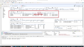
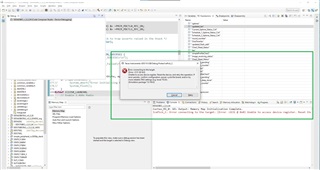
When I received the device, I connected the device into CCS debugger as guided in the ble_user_guide for "Connect the debugger to a running target".

https://dev.ti.com/tirex/content/simplelink_cc13xx_cc26xx_sdk_7_41_00_17/docs/ble5stack/ble_user_guide/html/ble-stack-5.x-guide/debugging-index.html 

response after connecting the debugger is shown in the attached image.

"Unable to access the device register, Reset the device retry the operation".

So I disconnected the device battery pack (CR2450X8 ) and reconnected it again.

After reconnecting the battery pack, device started advertising and also started working properly.

I had to HARD RESET the device.

This issue is being seen in many devices running on same firmware.

Please help me to find out the root cause and solution...

Thank you,

Dnyaneshvar Salve

  • Hi Dnyaneshvar Salve,

    When you try connecting the debugger, are you connecting the GND as well?
    It could be good to connect all the JTAG signals and also the RST and 3V3/GND (power with external power supply rather than battery).

    Also, can you check the status of the battery?

    What are the differences in device operation between:

    1. Factory test
    2. Field test

    Can you simulate the conditions in the Field in your Factory?

    What is meant by "not working"? Are there any LED indicators?

    Thanks,
    Toby

  • Hello Toby Pan,

    thank you for replying.

    Debugger connections are not changed and are similar when uploading code to new pcb.yes GND is there.

    battery voltage is 3.01vols.

    We have tested devices at factory for 48 hours continuous run. In those 48 hours CC2650 read the images (image byte array) every 5 minutes from external flash memory and displayed on epaper display.

    Also images were sent to devices using ble connection from android app. This is done 25 times per device.

    After 48 hours, we kept devices in idle condition for 12 hours.that is devices did not read any images from external flash or no images were sent to devices over ble connection.

    After 48 hr + 12 hr - we sent images over ble connection and device displayed them. This test is done 10 times per device.

    After that we dispatched the devices assuming everything is in normal state.

    At field, devices were expected to receive image data over ble and display. that didnt worked.

    so I told to check the advertising status. CC2650 were not shown in the ble scanner or light blue android app.

    At my office I also confirmed that device was not advertising.

    later I connected the debugger, but it failed as mentioned in the initial question.

    To simulate the field condition I have kept three devices in idle state, yesterday.

    There is no LED indicator on device. (we will be adding one in next pcb version).

    To mean by not working There is no ble advertising from device. I think the program is freezing.

    I have also kept one device which is printing one counter value in 5 seconds periodic function.

    counter value is incremented every 5 seconds.

    I can see counter value on UART terminal for this one device under testing.

    thank you,

    Dnyaneshvar Salve

  • Thanks for the details.

    I think the main difference could be the actual display image itself -- in the field it would be a different image than in factory.
    Can you try running a test on the returned device, where you load the actual images used in the field?

    Since the device is working ok after a reset, can you add a Watchdog to it?

  • Hello Toby Pan,

    thank you for replying,

    display image can not be the reason.

    Image is converted into the byte array and byte array is sent over the ble. let image be any, android converts the image into byte array.

    Suppose i have 7.5" Epaper display in system.

    resloution 800 X 480 (height X width). I get the (800*480*2)/8 (byte) = 96000 bytes are received at CC2650 side over ble.

    size of byte array is never mismatched with any image. we are testing this from last 2 years.

    The device that i am testing has not been used by customer. So no image was pushed to device.

    I have already implemented the watchdog into device and it works whenever I tested.

    I have opened the Runtime Object Veiw in CCS.

    and came to know that peak uses of Stack used by Task SimpleBLEPeripheral_taskFxn is showing 620 and and Stack size is 640. (image attached)

    Is this the possible reason?

    The problem is big issue for our product.We have already taken the orders from customers.

    We are ready to pay fees for dedicated support for this problem.

    please let us know if any kind of service like this is available.

    Thank you,

    Dnyaneshvar Salve

  • Yes, it is a concern if the stack peak so close to the stack size. There could be undefined behavior which would be resolved by a reset, so this matches the original symptom.

    Is there sufficient RAM remaining to increase that stack size to 1000?

    Since this is a BLE base example, I will loop in a BLE expert.

  • Hello Toby Pan,

    yes, sufficient RAM is available. I have set the Task stack size to1024.

    but I have already implemented the watchdog in code.it works well whenever tested.

    what is the reason whatchdog is not reseting the MCU even if there is stack overflow after 12 days long period.

    thank you,

    Dnyaneshvar salve

  • Hi Dnyaneshvar ,

    It is possible there may be a board issue that could be causing the behavior. Have you had your design reviewed at the SIMPLELINK-2-4GHZ-DESIGN-REVIEWS? Can you specify the percentage of devices affected? How many devices have been deployed and how many have been reported to have this issue?

    Best Regards,

    Jan

  • Hello Jan,

    thank you for replying,

    Our PCB designers have already taken the required precautions and followed the PCB design guidlines.

    But the designs are not reviewed at SIMPLELINK-2-4GHZ-DESIGN-REVIEWS.

    No.of devices deployed- 150 nos

    No.of devices affected- 16 nos

    percentage of devices affected- 24%


    Thank you,

    Dnyaneshvar Salve

  • Hi,

    Got it. Thank you for the clarity. I would highly recommend submitting a design review request. Our HW team will take a look at it ASAP and see if they have any concerns about the design. Regarding possible causes, it is a bit tough to say without having a way to reproduce this easily. Can you describe the environment where the behavior occurs and the environment where the devices are tested? Are they in similar temperature and humidity ranges?

    Best Regards,

    Jan

  • Hello Jan,

    Our hardware team will be submitting the designs soon.


    Our devices are deployed at controlled environments, locations are stores inside shopping malls and sofisticated air conditioned offices for giving product demos to clients.


    Yes they are in similar temperature and humidity ranges.

    thank you,

    Dnyaneshvar Salve

  • Hi Dnyaneshvar,

    Understood. Thank you for the details Make sure to provide this E2E thread as part of the design review in order for the HW team to consider the issue during their HW analysis in case they find a potential HW cause.

    Is it possible there may be an issue with the data transmission logic? If the behavior is happening at a customer site (with lots of BLE devices), then maybe there are packet collisions happening over the air which are causing incomplete data to be sent. Does your data transmission / reception logic account for incomplete data?

    Best Regards,

    Jan

  • Hello Jan,

    yes, our HW team will mention this e2e post link.

    The data reception logic takes care of the incomplete data.

    We have implemented the data integrity check function in code.

    When device receives the data packets (1packet = 200 bytes) periodic clock of 5 seconds is used to check for reliable - complete data packet reception.

    If there is partial data our code just discard the data.

    We have tested this many time by sending partial data and switching off the bluetooth on android device midway while sending data.

    thank you,

    Dnyaneshvar Salve

  • Hi Dnyaneshvar,

    Got it. Thank you for confirming. In this case, then the other possible cause could be s stack overflow or running out of heap during runtime. I know you had mentioned that you had already increased the stack size, but I think it may be worth it if a device could be flashed with the new image and placed under the exact conditions that caused another device to go into this issue. I understand this may be very difficult to do, but is this something that can be done?

    Best Regards,

    Jan

  • Hello Jan,

    In our code we haven't used dynamic memory allocation. (malloc, calloc, realloc, free).

    so there must not be any possibility of running out of heap memory unless there is bug present in the SDK example code. (please let me know if there is any)

    We printed the remaining heap memory on UART terminal and it is about 500 bytes. So I think heap memory isn't the issue.

    Yes, Stack peak uses is near the allocated stack size and there is a chance of stack overflow, but then is it possible that watchdog won't reset the mcu?

    I have simulated many possible cases with watchdog and it worked everytime.

    thank you,

    Dnyaneshvar Salve 

  • /*System Reset Feature Function*/
    void check_ble_packet_integity_and_EPD_sleep() {
        //check for ble rx error only when device is receiving image
        //if (image_receiving_status == 1) {
        	if ((conn_status == 1) ||(image_receiving_status == 1)){//this will do system reset if device ble is connected for more than 25 sec or if there is only partial image data is received
            current_image_packet_cnt = round_number;
            if (prev_image_packet_cnt == current_image_packet_cnt) { //if prev and current data packet count is same means no new data is being received then prepare for system reset
                skip_system_reset_cnt += 1; 						 //LET SYSTEM WAIT FOR BLE CONNECTION RECOVERY BY ALLOWING IT SOME TIME BY SKIPPING RESET
                //print_uart_str("\nskip_system_reset_cnt -> ");
                //print_uart_variable(skip_system_reset_cnt);
                if (skip_system_reset_cnt >= SYSTEM_RESET_SKIP_COUNT) {	//SYSTEM_RESET_SKIP_COUNT is 5 and periodic clock is 5 seconds, so 5*5 = 25 seconds
                    system_reset = 1;
                    //print_uart_str("\nsystem_reset_success");
                    HAL_SYSTEM_RESET();
                }
            } else {
                prev_image_packet_cnt = current_image_packet_cnt;	//if there is new ble data packet, copy current_image_packet_cnt into prev_image_packet_cnt
                skip_system_reset_cnt = 0;
    //          Device_Uptime_Status_Cnt = 0;
            }
        }
        //check if image is receiving and char2 is read by BLE central to read battery voltage and epd status
        //this is required if device status is called but no image byte array is sent
        //so calling epd_sleep is important
        else if ((image_receiving_status == 0) && (Char2_Read_Status == 1)) {
            EPD_Sleep(EPD_BUSY_PIN, EPD_DC_PIN, EPD_SCK_PIN,
            EPD_MOSI_PIN, EPD_CS_PIN);
            EPD_Sleep(EPD_BUSY_PIN_2, EPD_DC_PIN, EPD_SCK_PIN,
            EPD_MOSI_PIN, EPD_CS_PIN_2);
            //print_uart_str("\nEPD Sleep Done\n");
            Char2_Read_Status = 0;    //reset the flag
        }
    }

    This function used to reset mcu if ble is connected for more than 25 seconds and also there is no further incoming ble packet or partial ble packets are received.

    We have use HAL_SYSTEM_RESET(); function.

    I have verified that HAL_SYSTEM_RESET(); is hard reset, so no issue with that also.

    Also, In initialization code we taken care to convert the warm reset to pin reset,

    // convert warm_reset to pin_Reset(System_Reset)
    HWREG(PRCM_BASE + PRCM_O_WARMRESET) = 4;

    (Technical reference manual Section 6.8.2.4.37)

    I understand this may be very difficult to do, but is this something that can be done? Yes, Sure I will.

    But we must find out the root cause or else this problem will hit back us harder with larger number of devices from upcomng batch.

    thank you,

    Dnyaneshvar Salve

  • Hi,

    Yes, Stack peak uses is near the allocated stack size and there is a chance of stack overflow, but then is it possible that watchdog won't reset the mcu?

    I would be very surprised if the watchdog wasnt able to recover for this reason, but since we are not able to easily reproduce i think we should try to account for any possible cause to increase the chance we are able to solve the issue when the new firmware gets sent to the products in the field.

    But we must find out the root cause or else this problem will hit back us harder with larger number of devices from upcomng batch.

    Agreed. I think re-testing at locations where the behavior was confirmed to occur may give us some hints.

    Best Regards,

    Jan