Other Parts Discussed in Thread: SYSBIOS, CC2640, , ENERGYTRACE, CC2640R2F, SYSCONFIG
Tool/software:
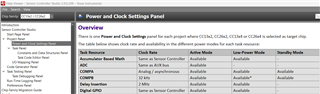
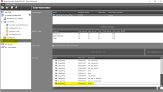
We use SimpleLink SDK CC13xx CC26xx version 6.10.0.29, and the TI tool CCS12:
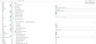
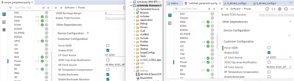
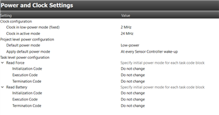
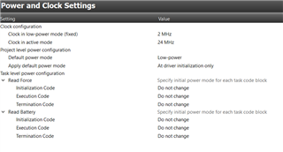
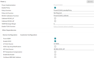
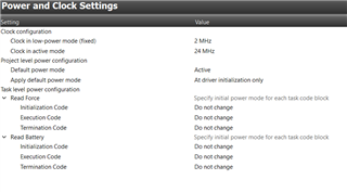
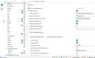
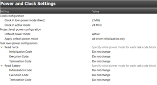
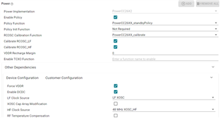
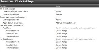
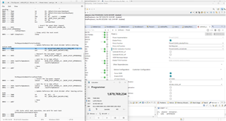
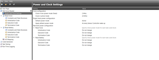
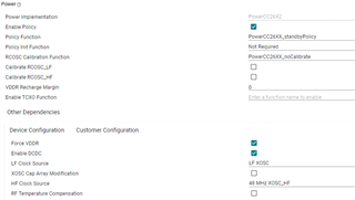
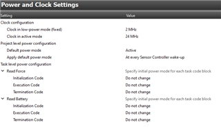
We use POWER_SAVING in the Compiler predefined symbols, and we enabled Standby policy in the same way as it is enabled in the TI FW app simple_peripheral in the same SDK 6.10.0.29: parameter comparison attached in a screenshot: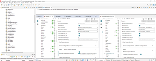
When we start our Firmware in this Power saving mode, it works well for approx. 1 minute, after that the data collection from sensor controller stops, and some timer(clock) related activities stop working as well.
Details:
1) We use Sensor Controller RTC-driven Alert interrupts to the main processor in the MCU. These interrupts/events invoke ADC read operations.
2) For LED on/off scheduling we are using timer (clock) APIs from file utils.c.
Util_constructClock: it calls ti_sysbios_knl_Clock_construct
Util_startClock: it calls Clock_start(handle) that calls ti_sysbios_knl_Clock_start
Question 1 for TI: Is it possible that the failures in these 2 above areas 1) and 2) are caused by a problem in the communication between drivers and the Power manager?
According to: SimpleLink SDK Power Management: MSP432, MSP432E4, CC13xx/CC26xx, and CC32xx User’s Guide (2019)
“1.3 Power Manager API
Driver development: A device driver communicates with the Power Manager to enable/disable access to its peripherals. “
The above spec is a bit old, Question 2 for TI: What is the best Power management TI spec to follow for our SDK CC13xx CC26xx version 6.10.0.29? We also used a TI spec (link below), but it is for a higher SDK version 6.40:
software-dl.ti.com/.../power.html
According to our battery usage measurements: our previous TI MCU CC2640 saved battery 2 times better compared to our new current prototype using 6.10.0.29: We also had POWER_SAVING there as a predefined symbol. We did not have .syscfg file with power policy options. We had the standby policy defined in a .cfg file, no longer used in the new SDK.