Other Parts Discussed in Thread: SYSCONFIG, CC2642R, CC2652R,
Tool/software:
Hi TI Engineer,
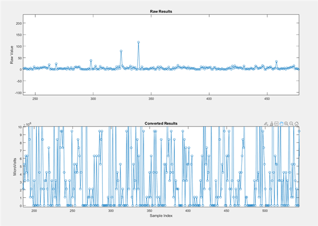
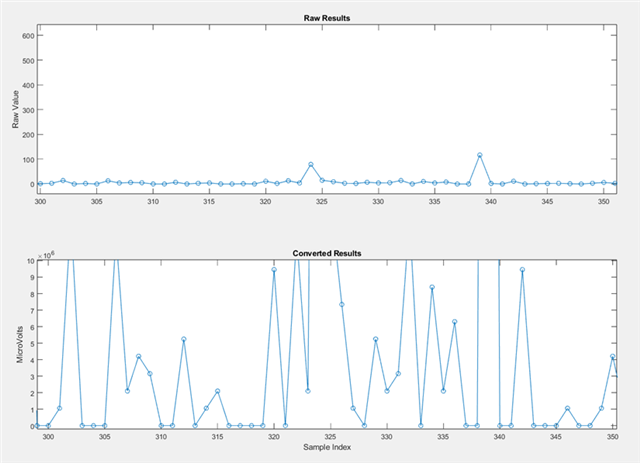
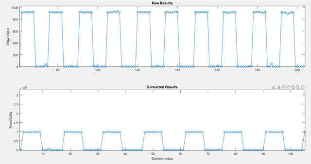
I am currently trying to use the ADC function in the example from C:\ti\simplelink_cc13xx_cc26xx_sdk_7_40_00_77\examples\rtos\CC26X2R1_LAUNCHXL\drivers\adcsinglechannel. I aim to receive signals from a signal generator and output them as charts using MATLAB. The inputs I have tried are sine waves and square waves, but the received signals are essentially garbled and do not resemble any recognizable waveforms. I have already confirmed that the signal generator is functioning correctly, as another component can receive the signals correctly.
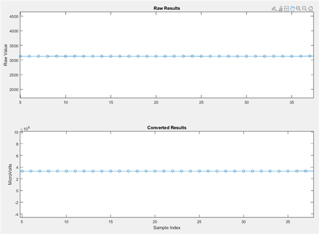
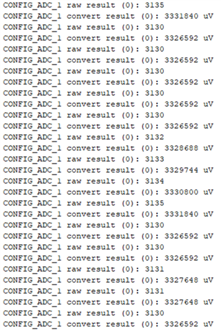
I will attach an image of the output below. Additionally, what confuses me is that when I connect DIO24 to the 3V3 pin, I can read a steady 3V3 signal. Does this indicate that the launchpad is functioning correctly? Or did I make a mistake in selecting the pin? I chose DIO24 and the GND on the top right. Or is there another coding issue I haven't considered? The code has basically not been modified, as I just want to test if the ADC functionality can work (UART functionality is operating correctly).
Please let me know if I need to provide the code. Thank you.
