This thread has been locked.

If you have a related question, please click the "Ask a related question" button in the top right corner. The newly created question will be automatically linked to this question.

CC2340R5: How to calculate the cap tim value?

Part Number: CC2340R5

Tool/software:

In swra640 we have a table to look up to the cap-array delta value and the measured capacitor bias value:
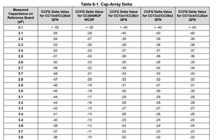
Where can I find a similar table for CC2340? The Q1 and Q2 value can only be positive in SmartRF Studio 8, which is different than CC26xx.

Best regards,

Shuyang

  • Hi Shuyang,

    You are correct, the valid settings for CC2340 are different from the value listed in the table for other devices. For CC2340Rxx the easiest way to determine the appropriate capacitor value is to use SmartRF studio. By monitoring the CW output on a spectrum analyzer and adjusting the capacitor value until the frequency is at the desired value the appropriate capacitor setting can be determined.

    BR,

    Jake

  • Hi Jake,

    Is there a formula or a table for it? At least can we know which numbers represent positive offset and which ate negative?

    The customer tried from 0 all the way to the maximum number and did not find a good offset value, having this table will improve the customer experience and avoid confusion which I would strongly recommend to have it in our document.

    BR,

    Shuyang

  • Hi Shuyang,

    It's very surprising that the customer did not find a suitable value. How far off from the target frequency were they? What crystal are they using? What is the target load capacitance? What does the crystal layout look like? Have they had a schematic review done? There are a lot of questions you need to ask to help debug the issue. 

    I don't have any data from production parts but here is data measured from a pre-RTM device which covers a range from about 2.5pF to 11pF which would cover the range of 48MHz crystal load capacitance that we support, the absolute values may have changed since but I expect the range would remain the same which, I still don't know how this helps at all if they have already tried all these setting and failed:

    Code Capacitance
    0 2.57E-12
    1 2.66E-12
    2 2.76E-12
    3 2.85E-12
    4 2.95E-12
    5 3.04E-12
    6 3.14E-12
    7 3.23E-12
    8 3.33E-12
    9 3.42E-12
    10 3.51E-12
    11 3.61E-12
    12 3.70E-12
    13 3.79E-12
    14 3.88E-12
    15 3.97E-12
    16 5.72E-12
    17 5.60E-12
    18 5.49E-12
    19 5.37E-12
    20 5.26E-12
    21 5.15E-12
    22 5.03E-12
    23 4.91E-12
    24 4.80E-12
    25 4.68E-12
    26 4.57E-12
    27 4.45E-12
    28 4.33E-12
    29 4.21E-12
    30 4.09E-12
    31 3.97E-12
    32 5.97E-12
    33 6.12E-12
    34 6.26E-12
    35 6.41E-12
    36 6.55E-12
    37 6.69E-12
    38 6.84E-12
    39 6.98E-12
    40 7.12E-12
    41 7.26E-12
    42 7.40E-12
    43 7.55E-12
    44 7.69E-12
    45 7.83E-12
    46 7.97E-12
    47 8.10E-12
    48 1.10E-11
    49 1.08E-11
    50 1.06E-11
    51 1.04E-11
    52 1.02E-11
    53 1.00E-11
    54 9.84E-12
    55 9.65E-12
    56 9.46E-12
    57 9.26E-12
    58 9.07E-12
    59 8.88E-12
    60 8.69E-12
    61 8.49E-12
    62 8.30E-12
    63 8.10E-12
  • Hi Jake,

    Thanks for the data. The issue is solved with a fine tune Q1 and Q2 value, turned out the customer did not try all the values although they told me so...

    However, I think a table like this will still help a lot to the customer when you are trying to tune their customer boards, the hardware design document on CC26x2 is so helpful and frequently used, it will be great if we can have one for CC2340 platform.

    Best regards,

    Shuyang