This thread has been locked.

If you have a related question, please click the "Ask a related question" button in the top right corner. The newly created question will be automatically linked to this question.

CC2340R2: External Clock running at 31.25kHz?

Expert 3740 points
Part Number: CC2340R2
Other Parts Discussed in Thread: SYSCONFIG,

Tool/software:

Hi team,

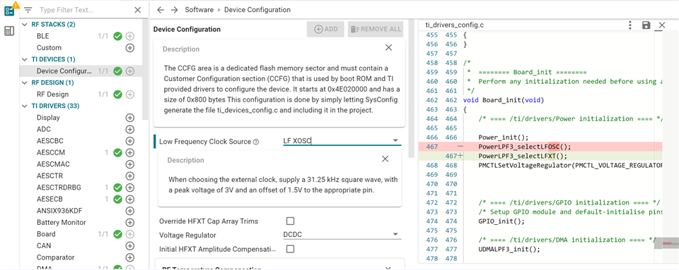
Customer is switching from using the internal low frequency clock to the external clock. Their external clock is running at 32.768kHz but the note inside of Sysconfig (version 1.20.0) looks like it is saying that it should be running at 31.25kHz. Is this right or is this a typo in the description? If correct, could you explain?

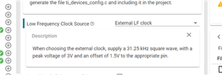
The LF crystal and LF osc are both 32.768kHz, so it doesn't make sense to me that the External LF would not also be 32.768kHz. I also can't find any reference in the datasheet or TRM for this 31.25kHz clock requirement.

Thanks,

Luke

  • Heya Luke!

    It's really intended to be 31.25 kHz.  Here is PowerCC23X0.c where it is briefly explained.  It may be possible to create a custom PowerCC23X0.c CKMD_O_LFINCOVR register value to compensate (i.e. 0x1E8480 for 32.768 kHz) but this is not an official recommendation as I have not tested/validated such a solution. I am also compelled to mention that they should be using a peak voltage of VDDS and an offset of VDDS/2.  There are several instances where 3V / 1.5V would violate datasheet specs depending on the VDDS range.  I am supplying this feedback to the TI Drivers Team as well to understand whether any improvements can be made.

    If they are using a 32.768 kHz external crystal oscillator they should select LF XOSC.

    Regards,
    Ryan

  • Hi Ryan! 

    We may need some additional help with this one. They believe that they were discouraged a while ago from using the LF XOSC (internal to CC2340R2) but they may be misunderstood. Some of the reasons they thought we may not recommend are due to the internal oscillator not being accurate and that the internal oscillator consumes more power. Is there any reason that they should not be using the internal oscillator? (Option 1)

    The old design that this new part is replacing, had another processor supplying the 32KHz signal, And we hope not to modify that codebase, so that is the primary reason we want to use the 32kHz signal.

    (Option 2) Supply the 32kHz signal and create their own PowerLPF3_selectEXTLF() function that sets the CKMD_O_LFINCOVR register value to 0x1E8480. We could copy the function and update the math for 32kHz and call our new function inside of the Board_init().

    What is the downside to doing this?  Will the timing of the UART signals be just as good? Will the power usage be just as good?

    I checked the SysConf tool with our project file and I think these are the places in our code that uses the LFXT clock source:

    • Watchdog
    • Power management.

    This is all the info I have from the customer. Could you share your input on which option would be best to move forward with?

    Thanks,

    Luke

  • One point of clarification which may not be clear in the documentation:

    • SysConfig LF XOSC = CC2340R2 LFXT, this is the external 32 kHz LF oscillator and is the recommended approach for accuracy
    • SysConfig LF RCOSC = CC2340R2 LFOSC, this is the internal 32 kHz which is not as accurate.

    Please refer to the PowerCC23X0.h documentation, device Datasheet, and SysConfig output ti_drivers_config.h to further understand.

    The downside to Option 2 is that it is not tested by TI at the moment and should be validated by the customer.  It should not affect the UART accuracy which relies on the HF clock and power usage will be the same as if the original 31.25 kHz were used.  The LF clock is crucial for peripherals which operate in Standby low-power mode (8.11 Power Management of the datasheet).

    I always recommend a 32 kHz external oscillator connected to DIO3_X32P/DIO4_X32N with load capacitors.

    Regards,
    Ryan

  • Ryan,

    Thanks for the explanation! I've shared these recommendations with the customer and will see what route they'd like to go down now. Seems like the LF XOSC will be the easiest/most solid solution. 

    One thing to note (I'm sure you are already aware) is the CLK_01 Errata talking about LFOSC which we should avoid them using anyways based on the feedback above. 

    Thanks,

    Luke

  • Ryan,

    Some additional comments...

    They don't think they want to put an actual oscillator on the board, due to added cost. They'd rather send a signal from the other processor. Can we send the signal from the other processor and still pick LF XOSC? If so, then I think that is what they will want to do.  If not, then there's more thinking to do.

    Best,

    Luke

  • If using a signal from a separate processor they should choose external LF clock.

    Regards,
    Ryan

  • Ryan,

    Understood, I chatted with them and they plan to supply the 32kHz signal and create their own PowerLPF3_selectEXTLF() function that sets the CKMD_O_LFINCOVR register value to 0x1E8480.  They will copy the function and update the math for 32kHz and call the new function inside of the Board_init().

    After reading through PowerCC23X0.c a bit, it is still a bit strange that the TI SDK expected a 31.25kHz signal here instead of the 32.768kHz, which is what started all these questions. Is there any additional context you can add to share with them? Anything that may affect this plan? Let us know.

    Thanks for the support!

    Luke

  • Hi Luke,

    I'll ask the TI Drivers Software Development Team for details and let you know when they respond.

    Regards,
    Ryan

  • Hey Ryan,

    Did you end up hearing back from the Drivers team on this one?

    Best,

    Luke

  • I have not, I'll ping them.

    Regards,
    Ryan

  • "From a systems point of view maybe 31.25kHz makes a little more sense.  For example given an external MCU supplying the clock. In most cases it wouldn’t be possible to output an accurate 32.768kHz clock if divided down by a whole number clock divider. 31.25kHz is a lot easier to get to from whole number dividers. For example from a 40MHz clock you’d have to divide by 1220.7 (not feasible) to get to 32.768kHZ vs an even 1280 to get to 31.25kHz. If the external MCU supplying the clock can just pass 32.768kHz from it’s clock system then I guess the challenge is reversed."

    "As you mentioned, a workaround would indeed be to override the “override” register with a value that corresponds to the chosen frequency, making sure to do so *after* PowerLPF3_selectEXTLF has been called."

    Regards,
    Ryan

  • Thanks for getting this info, Ryan!

    -Luke