Other Parts Discussed in Thread: CC2340R5
Tool/software:
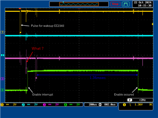
Hi TI team.
While I have a similar question, please tell me the following method.
I want to obtain the low pulse width (about 16 microseconds) output from another IC using the LGPTimer feature.
Can it be obtained through the following process?Please let me know.
 /* LGPTimer Settings */
 LGPTimerLPF3_Params_init(&lgpt_params);
 lgpt_params.hwiCallbackFxn = pulse_measure;
 lgpt_params.channelProperty[0].action = LGPTimerLPF3_CH_PULSE_WIDTH_MEASURE ;
 lgpt_params.channelProperty[0].inputEdge = LGPTimerLPF3_CH_EDGE_BOTH ;
 lgpt_handle = LGPTimerLPF3_open(CONFIG_LGPTIMER_0, &lgpt_params);
 LGPTimerLPF3_enableInterrupt(lgpt_handle, LGPTimerLPF3_INT_TGT);
 LGPTimerLPF3_start(lgpt_handle, LGPTimerLPF3_CTL_MODE_UP_PER);
 ...

 void pulse_measure(LGPTimerLPF3_Handle lgptHandle, LGPTimerLPF3_IntMask interruptMask)
 {
    /* Get pulse period */
    uint32_t pulse_period = LGPTimerLPF3_getChCaptureVal(gh_lgpt1_handle, LGPTimerLPF3_CH_NO_0);
 }
Regards.