Because of the Thanksgiving holiday in the U.S., TI E2E™ design support forum responses may be delayed from November 25 through December 2. Thank you for your patience.

CC2340R5-Q1: Pattern antenna or chip antenna

Part Number: CC2340R5-Q1

Tool/software:

We are considering a compact automotive module using CC2340R5-Q1.

When considering a product that fits into a substrate size of about 35 mm x 20 mm
Pattern antenna or chip antenna to be the minimum configuration
If you have any recommendations for the minimum configuration of pattern antennas or chip antennas, please let us know.

  • Hello,

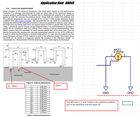
    We have several antenna options that are detailed in our application note AN058 linked here. We typically recommend the inverted F antenna that is described in this app note but this may be too large for your compact design. In addition to the antennas detailed in the AN058 app note, we've also identified the following two offerings from Kyocera AVX as potential options Option 1 and Option 2. Just please keep in mind that the Kyocera AVX antennas have not been fully evaluated by TI and you would need to contact them with any design and layout/implementation questions you may have. 

    Thanks,

    Andrew

  • Thank you for your response
    If you refer to the following URL
    31Pin antenna terminal to antenna
    Could you please provide the recommended circuit and constants?
    http://www.ti.com/lit/swra117

  • Hello,

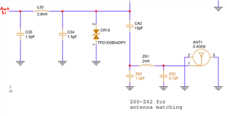
    The recommended RF front end is shown below. Keep in mind that the antenna matching (components Z60, Z61, and Z62) will need to be measured and adjusted for your design as differences in layout and stackup can greatly affect the required match for maximum power transfer.

    Regards,

    Andrew