This thread has been locked.

If you have a related question, please click the "Ask a related question" button in the top right corner. The newly created question will be automatically linked to this question.

LP-EM-CC2340R5: UART2ECHO long response

Part Number: LP-EM-CC2340R5

Tool/software:

Hello,

I have 2 dev boards with CC2430R5 that I started to play with. I am starting with uart2echo example to see how uart is working and it seems a little intricated. I have several questions that I'm hoping to get

1) is there some documentation for the code, like architecture used in simplelink for this and other? (like RF echo, etc)

2) I have ran the example and it seems that the response is about 130 ms, which seems high. is there a way to decrease this to 10 ms or less? 

Thank you in advance,

Mircea

  • Hello Mircea,

    I hope you are doing well. In CCS if you navigate to syscfg, click on the UART driver (or target driver) and click on the "?" mark it will show a menu with "examples" with a hyperlink to extra SDK documentation on that particular driver, this is quite useful to reference and read about.  

    On the topic of response, are you using PuTTY? I will try to replicate this response time myself with the driver but 130ms does seem high.

    Thanks,
    Alex F

  • Hi Alex,

    Thanks for the answer. I am using docklight (which is the same), and on other projects I can confirm it works well. 

    I cannot see the question mark:

    I worked with IAR and older version of CCS and I'm not that familiar with it.

    On the side note, I can't see to manage to use Go To Definition in CCS, nor use the find in project (it doesn't search in all the files included). Maybe you can also help on this.

    Have a great day,

    Mircea

  • Hello Mircea,

    The "?" mark is right next to the driver name, it is a little small so its hard to notice! 

    and after clicking on it we can see the menu with hyperlinks:

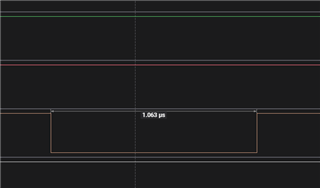
    Using the default uart2echo example from the 8.10 F3 SDK I read a latency (per character) of 1us, reference my GPIO addition which I used for latency timing below:

        while (1)
        {
            bytesRead = 0;
            while (bytesRead == 0)
            {
                GPIO_write(CONFIG_GPIO_LED_0, CONFIG_GPIO_LED_ON);
                status = UART2_read(uart, &input, 1, &bytesRead);
    
                if (status != UART2_STATUS_SUCCESS)
                {
                    /* UART2_read() failed */
                    while (1) {}
                }
            }
    
            bytesWritten = 0;
            while (bytesWritten == 0)
            {
                status = UART2_write(uart, &input, 1, &bytesWritten);
                GPIO_write(CONFIG_GPIO_LED_0, CONFIG_GPIO_LED_OFF);
                if (status != UART2_STATUS_SUCCESS)
                {
                    /* UART2_write() failed */
                    while (1) {}
                }
            }
        }

    Thanks,
    Alex F