CC2642R: Performance issue observed after fuse blown in CC2642, MSP430FR2673

Part Number: CC2642R
Other Parts Discussed in Thread: MSP430FR2673, MSP-GANG, MSP-FET

Tool/software:

Hi Team,


We have used CC2642, MSP430FR2673 devices in one of PCB’s.


The PCBs are in production, loaded FW to PCBs via production testers . All tests pass & functionality is good.


When we done Fuse blown via Gang programmer in CC2642, MSP430. All tests pass. Manually power on/off the HW PCB’s functionality is not working as expected.


To address this issue what are the suspected areas need to verify. Let us share your thoughts.


Regards,

Rajani     

  • Hi Rajani, 

    Thank you for reaching out. 

    You said that the board works well until you power it off? (i.e. after power it back on, the behavior is not as expected?) - Is it correct? 

    Would triggering a reset produce the same faulty behavior? 

    What are the performance issues observed in that case? Do you have some reports you could share? 

    Also, can you provide some details on the way CC2642 and MSP430FR2673 are interfaced? Which one of these devices is the one you suspect causing the issue? 

    Best regards, 

  • Hi, 

    Thank you for immediate reply.

    board works well until you power it off? 

    We ran production test command like FW load, read FW version, time stamp write/ read,  slno write/read MAC address read/write. All results are showing pass.

    1. Ran the boards without MSP430 Fuse blown

    Result- All test cases passed and manually powering on the UUT, see the boards are working Power on LED turn on

    2. Ran the boards with MSP430 Fuse blow enabled

     Result- All the test cases passed and while manually powering on only 3 boards showing expected behaviour Power on LED turn on and 4 boards not showing any expected condition. ( No LED indication) Looks to me went dead lock condition.

    CC2642 to MSP430FR2673 interface is I2C bus.  LED's RGB are controlling via MSP430 chip

    Regards,

    Rajani

  • Hi Rajani, 

    Let me pull in the MSP430 team in the discussion. 

    As the team is located in another site, some delay should be expected. Please bear with us. 

    Best regards, 

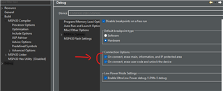
  • For MSP430FR2673, you can use the CCS to unlock the device as below, but the original image will be erased.

    By the way, how do you enabled the fuse blow?

  • Hi,

    MSP430 we are using FET Pro tool.

     Update MSP430 FW, after all test cases are completed & passed, then only do fuse blow in MSP430.

    Regards,

    Rajani

  • Two comment from myside:

    1. using a ti's demo code like gpio toggle to see if any problem with fuse blow

    2. due to the fr2673 is e-fuse that using JTAG signature below, you can try to modify it directly in your image file

  • Hi,

    If we send any wrong commands to blow fuse, is it create mass erase command, so boards are blank behaviour.

    Is it relating to the FET430 pro commands or any timing issue. Some Boards are working some are showing failure condition.

    Regards,

    Rajani    

  • Any log information from FET430 when it failed?

  • Hi,

    Please find the log file.

    Noticed without fuse blow of MSP430, out of 5 PCB's found issue one of PCB.

    ARM MSP log.txt
    1. ARM FLASHING LOG:
    
    ARM Flashing
    =====================================
    Communication initialization...................	 OK
    ... JTAG Chain -> Disabled
    ... JTAG IR size = 10,  No of TAPs = 2
     #1:  initialization error
     #2:  initialization error
     #3:  initialization error
     #4:  initialization error
     #5:  initialization error
     #6:  OSC=48.31 MHz, Sys.CLK=48.31 MHz
    Erasing memory.....................................	 done
    Selected Memory Blank Check.
     #6:  ..	 OK
    Flash programming.................................
     #6:  ..	 OK
    Verifying checksum...........................
     #6:  ..	 OK
    Writing Locking Registers .........
     #6:  ..	 OK
    Writing Debug Registers .........
     #6:  ..	 OK
     -------- D O N E --- ( run time =   7.0 sec.)
    
    
    2. MSP FLASHING LOG WITHOUT FUSEBLOW:
    
    
    MSP Flashing
     == Auto Program ===
    =====================================
    JTAG communication initialization....	 OK
    Verifying Security Fuse ....................	 OK
    ...	 OK
    Erasing memory ...............................	 done
    JTAG communication initialization....	 OK
    Flash programming ....................	 done
    Verifying check sum .......................	 OK
     -------- D O N E --- ( run time =   2.0 sec.)


    2. MSP FLASHING LOG WITH FUSEBLOW:
    
    MSP Fuseblow
     == Auto Program ===
    =====================================
    JTAG communication initialization....	 OK
    Verifying Security Fuse ....................	 OK
    Erasing memory ...............................	 done
    JTAG communication initialization....	 OK
    Flash programming ....................	 done
    Verifying check sum .......................	 OK
     -------- D O N E --- ( run time =   2.0 sec.)


  • What's the interface do you use to program the MSP430? 4-wire JTAG or SBW?

    How long do you use the wire from the programmer to your target board? The recommend length is <15cm.

  • Hi,

    Program via JTAG. Length used less than 15cm

    Able to program all PCBs via production tester. 

    Observed -

    One PCB CC2642 with no firmware present. Not clear it had been erased, or if it had never been programmed at all. MSP430 also empty, but the fuse was blown.

    The interface MSP430FR2673 to main controller CC2642 is I2C. 

    Found performance issues after power OFF/ON.  Intermediate issue. Out of 5PCB's 1 PCB result is not as per expected.     

    Is any timings need to improve (Erase, program etc)

    Flash memory is erasing if any conditions?

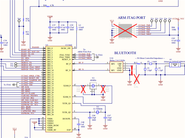
    Below configuration used in PCB level. Is it OK or need to improve. 

  • Could you help to modify the pull down capacitor C62 from 0.1uF to 2.2nF?

    By the way, could you show me the settings of the MSP-GANG gui?

  • Hi Team, please find the MSP430Fxx setup configuration file.

     MSP430 config.cfg 

  • It seems not a MSP-GANG's config file, what's the program tool do you use?

  • Hi, 

    MSP430 Gang-JTAG/BSL 

  • It seems I have not hear such tool before. Do you have some picture about the program tool and it's gui? And the link where to download its GUI?

  • It seems I do not have such tool, but back to your issue. Few test could you help to do for debug?

    1. Do you have a msp430 launchpad or MSP-FET on your side?

    2. For the failed device you can't do re-program by the JTAG with the tool of FlashPro430, right?

  • Hi, 

    Found intermediate issue without Fuse blown of MSP430 device.

    My location i tried multiple times load FW version via MSP-FET430UIF tool.   Not found any functional issues. 

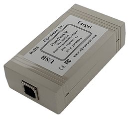
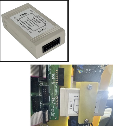
    If use longer JTAG cable as shown below will create problem? Is change of 10.1uF to 2.2nF at JTAG improves reset sequence.

    ...  

  • Hi,

    Please check once below configuration parameters. Any configuration parameter needs to improve. Problem found when with MSP430FR2673 .. 

    ;============= MSP430Fxx setup =============

    PasswFileName
    ScriptFileName
    AppendPasswData ................................................................
    SelectedProcessorIndex 610
    PowerFromPODEnable 1
    FlashEraseModeIndex 1
    EraseInfoSegmA 0
    EraseInfoSegmB 0
    EraseInfoSegmC 0
    EraseInfoSegmD 0
    EraseFlashSegmA 0
    EraseFlashSegmB 0
    EraseInfoA_F2xx_En 0
    Interface 0
    CommSpeedIndex 2
    JTAGSpeedIndex 1
    ResetTimeIndex 0
    ResetPulseTime 0
    ResetIdleTime 0
    Reset3stModeEn 0
    VccAsResetOffTime 50
    ApplProgramRunTime 0
    JTAGResetVccToggleTime 50
    ApplyDCOcalEn_F2xx 1
    ReleaseJtagState 0
    RunTimeTDIgenEn 0
    TDIgenDivider 1
    TDIgenPrescaler 0
    DCOExtResistorEn 0
    DCOcalData0_En 0
    DCOcalFreq0 4000
    DCOcalData1_En 0
    DCOcalFreq1 4000
    DCOcalData2_En 0
    DCOcalFreq2 4000
    DCOcalData3_En 0
    DCOcalFreq3 4000
    DCOcalData4_En 0
    DCOcalFreq4 4000
    DCOcalData5_En 0
    DCOcalFreq5 4000
    DCOcalData6_En 0
    DCOcalFreq6 4000
    DCOcalData7_En 0
    DCOcalFreq7 4000
    DCO_defined_addr_en 0
    UnlockJTAGEn 1
    CheckDCOconstants_F2xx 1
    RetainInfoCalData 1
    RetainDefinedData 0
    FlashReadModeIndex 0
    ReadInfoSegmA 0
    ReadInfoSegmB 0
    ReadInfoSegmC 0
    ReadInfoSegmD 0
    ReadFlashSegmA 0
    ReadFlashSegmB 0
    ReadDefMainMemEn 0
    EraseDefMainMemEn 0
    VerifyModeIndex 2
    SerializationEnable 0
    SNDispFormatIndex 0
    SNMemFormatIndex 1
    ModelTextEnable 0
    ModelTextSize 2
    ModelDataType 0
    BlowFuseEnable 0
    ApplicationStartEnable 0
    SNInfoMode 0
    SNExistWarnEn 1
    RemoveCodefromSNlocationEn 0
    CodeFileReload 0
    Custom_SN_size 4
    BarCodeReaderEnable 0
    BarCodeAutoStartEnable 0
    PostAmbleIndex 0
    VccIndex 5
    Vcc_in_mV 3300
    BSLEnhSecurityEn 0
    BSLEnhSecurityIndex 0
    BSLAppendPasswordEn 0
    BSLPasswSelectorIndex 0
    BSLOnePasswOnlyEn 0
    BSL_Xv2_Code_ReadEn 0
    BSL_Xv2_Code_WriteEn 0
    EraseResetSectorIfFailedEn 0
    BSLPasswSelNotShow 0
    DispSkipBlankLines 1
    CS1_Enable 0
    CS2_Enable 0
    CS3_Enable 0
    CS4_Enable 0
    CS_type_index 0
    CS_Init_index 0
    CS_Result_index 0
    CS_code_overwrite_en 0
    Graph_MeasureMode_index 7
    Graph_SamplingRate_index 3
    Graph_MeasureCurrent_index 0
    Graph_Ratio1 25
    Graph_Ratio2 75
    Graph_Scale2 1
    Graph_InvAlpha 10
    Graph_IgnoreCurrentBelow 5
    TargetsEnableMask 63
    EraseFlashStart 0x1100
    EraseFlashStop 0xFFFF
    RetainDataStart 0x1000
    RetainDataStop 0x1000
    ReadStartAddr 0x1100
    ReadStopAddr 0xFFFF
    SNStartAddress 0x1000
    ModelTextStartAddr 0x1000
    Starting_SN 0x0000
    Ending_SN 0x0000
    DCO_base_address 0x10F0
    JTAG-Clk-frequency 0x07D0
    CS_Polynominal 0x0000
    CS1_StartAddress 0x1000
    CS1_EndAddress 0x1000
    CS1_ResultAddress 0x1000
    CS2_StartAddress 0x1000
    CS2_EndAddress 0x1000
    CS2_ResultAddress 0x1000
    CS3_StartAddress 0x1000
    CS3_EndAddress 0x1000
    CS3_ResultAddress 0x1000
    CS4_StartAddress 0x1000
    CS4_EndAddress 0x1000
    CS4_ResultAddress 0x1000
    MCU_name MSP430FR2673
    SNFilePathAndName
    ModelCode 00 00

  • It seems you have not load the picture of the JTAG cable. Any way, the recommend length is less than 15cm. To change the NRST pin pull down capacitor from 0.1uf to 2.2nf just to avoid to use SBW mode that capacitor higher than 2.2nf will make the communication failed. 

  • Hi,

    Please find cable used in production tester setup. These tools used multiple testers did not find any Issue. only one test set up observed intermediate issue.

    Cap replaced, PCB placed into tester, programmed (No Fuse blown). First time functionality is not good. Same PCB repeated 4 times. placed into tester, programmed (No fuse blown). Functionality is good. 

    Expected test results: All test results pass in production tester. After power on the PCB via power supply, power on sequence supposed to be good. Red LED is Ok, White LED OK.

     The red LED means the MSP430 (cap' sense) controller is good (that red LED blink is generated by the MSP430 on bootup, not commanded by CC2642).  The white LED's (all three banks) are commanded on when the cc2642 boots up.

     Is CC2642 is not booting properly & unable to communicate to MSP430?

    Review once CC2642 side


  • Cap replaced, PCB placed into tester, programmed (No Fuse blown). First time functionality is not good. Same PCB repeated 4 times. placed into tester, programmed (No fuse blown). Functionality is good. 

    That mean the cap replacement have no help, right?

    If so, could you help to try the solution that I provided to you before that modify your firmware file directly to disable the JTAG interface? If you don't know how to modify it, you can send me your firmware file by TI-TXT format I can help to modify it.

    If you don't know how to generate the TI-TXT format you can refer to 

    Generate_txt_file.pdf

  • Hi, 

    Cap replacement is not resolved problem.

    Finally, problem is solved. after increasing the power cycle delay for ARM CC2642 in Testers software.

    Tested 5 PCBs in Fuse blown condition & functionality

    Thank you, so much timely shared additional information, to focus on identification of Root cause. 

    Reagrds,

    Rajani

  • Oh, thanks to share the root cause.